
Wave division multiplexing replacement of serialization

a technology of serialization and wave division, applied in the field of optical data transmission, can solve the problems of introducing timing and complex circuitry, etc., and achieves the effects of reducing electronic interference, reducing the size of data carrying cables, and increasing bandwidth capabilities

Active Publication Date: 2011-08-09
SEMICON COMPONENTS IND LLC
View PDF9 Cites 0 Cited by
  • Summary
  • Abstract
  • Description
  • Claims
  • Application Information

AI Technical Summary

Benefits of technology

[0009]The present invention provides advantages of minimizing the size of data carrying cables, reducing electronic interference, increasing bandwidth capabilities, and overcoming timing issues related to serialization / de-serialization.
[0013]Optical fibers have a number of benefits. The bandwidth is in the gigaHertz range, they are small, and electrostatic interference does not affect optical signals. The physical cable may be smaller and more reliable than a many conductor copper wire cable meant to carry parallel data.

Problems solved by technology

The number of wires in the cable is reduced, but timing and complex circuitry issues are introduced.

Method used


Image

  • Wave division multiplexing replacement of serialization
  • Wave division multiplexing replacement of serialization
  • Wave division multiplexing replacement of serialization

Examples


Embodiment Construction

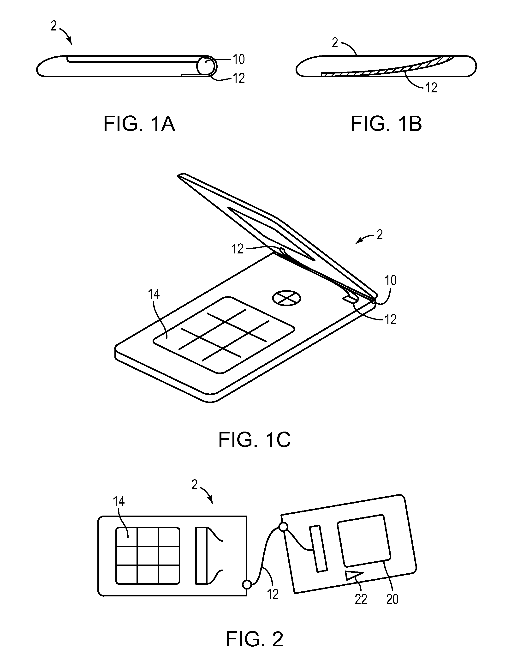
[0026]FIGS. 1A, 1B, 1C and 2 illustrate one application of the present invention. A “flip phone”2 is shown with a hinge 10. The hinge includes a thin optical cable 12 that is arranged to allow the full range of motion needed to open and close the flip phone.

[0027]The optical cable may be arranged to carry the optical signals back and forth via an electronic / optical interface 16 traversing the hinge 10 between a keyboard 14 and a display screen 20 and camera 22. In the illustrative example, the optical cable 12 extends from one side of the device to the other and complies with the opening of the device by twisting to reduce the bending radius.

[0028]In a stationary phone or a hand held electronic personal assistant, the present application may dispense with the optical cable and simply run an optical layer interface, as discussed below.

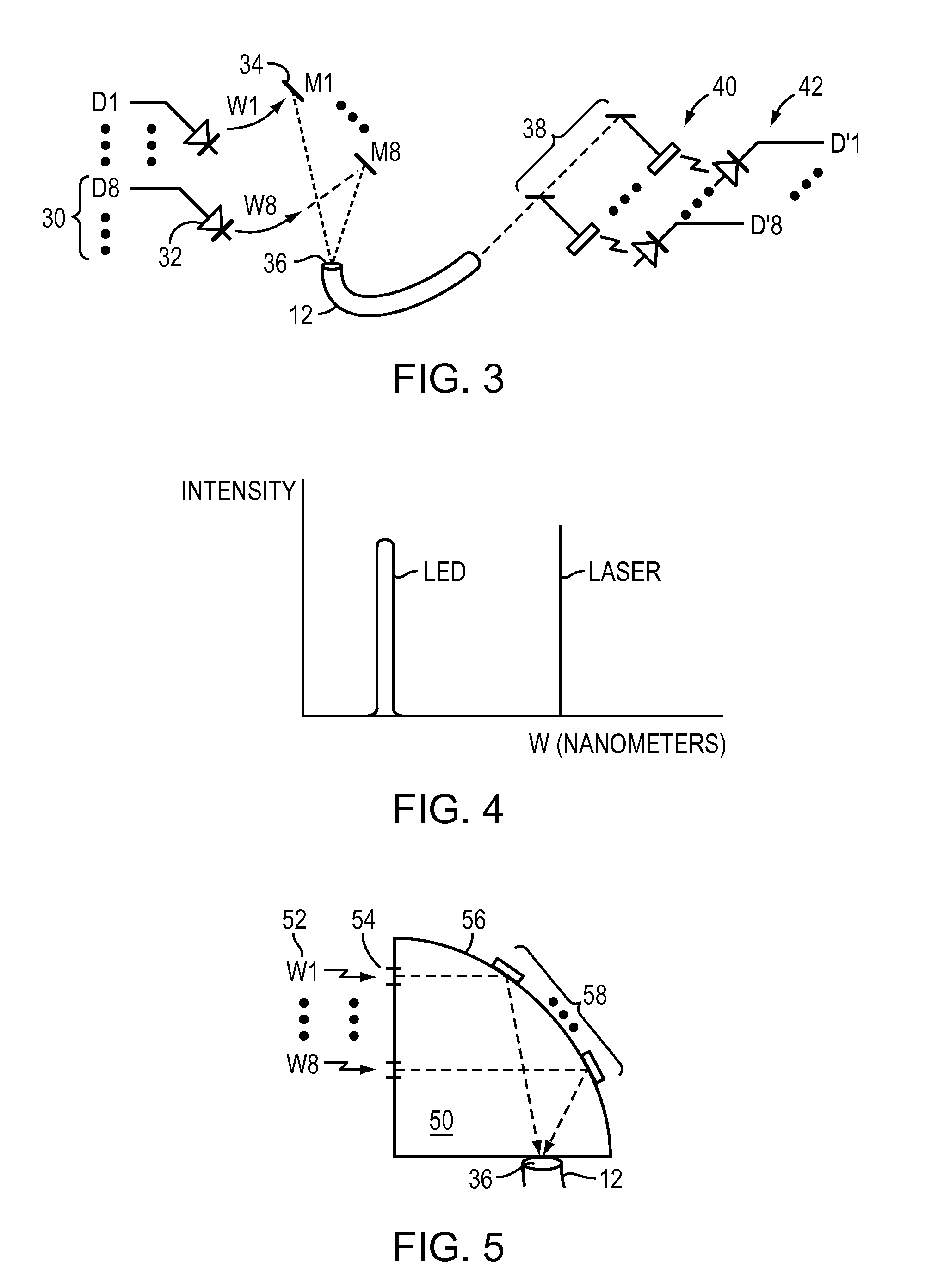
[0029]FIG. 3 illustrates electronic signals 30 driving LED's 32. The light from the LEDs are arranged cover from the visible spectrum into the infrared...


PUM


Abstract

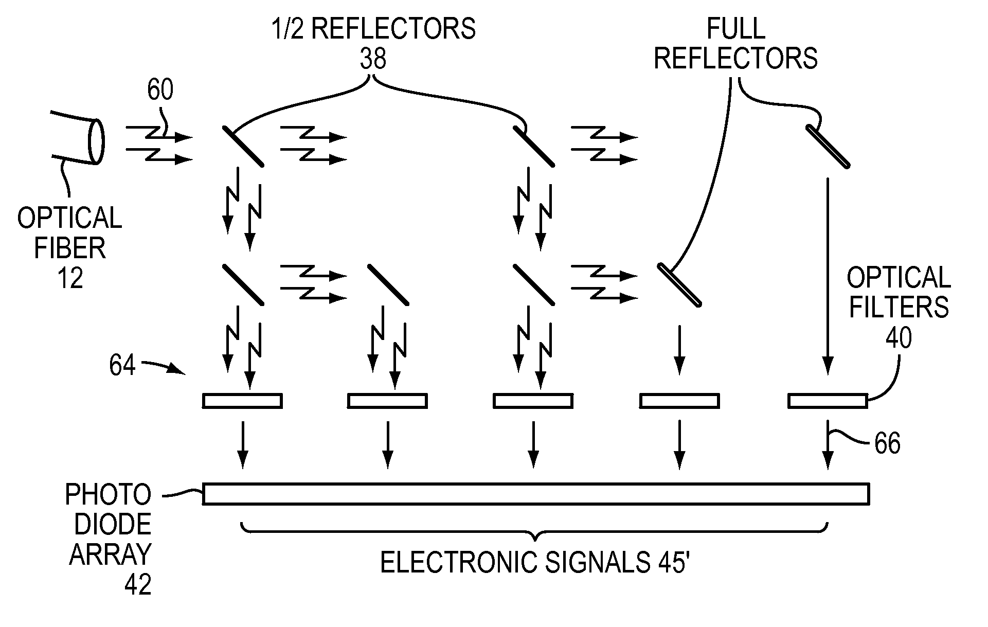
A WDM system is used to transfer bytes of data between keyboard, display and camera portions of a hand held device. The data signals are converted into light wavelengths via lasers or LEDs of differing wavelengths and transported over an optical fiber cable. Mems devices help direct the wavelengths to the optical cable and mems devices may be used at the receiving end. The receiver illustratively has a photodiode array to receive the different wavelengths and produce electronic signals. Optical filters and micro-ring resonators may be employed.

Description

BACKGROUND OF THE INVENTION[0001]1. Field of the Invention[0002]The present application relates to optical data transmission, and more particularly to converting parallel electronic signals to optical signals and wavelength multiplexing those signals in parallel over optical fiber and converting back to parallel electronic signals.[0003]2. Background Information[0004]Transmitting parallel data over wire cables usually entails using many conductors (copper wires). In these cases, EMI (electromagnetic interference), ground loops, and reliability issues must be considered by designers. This is especially true where the wires comprise part of a hinge, e.g., in flip or clam shell type of cell phone, or “flip phone”). One approach to these issues has been to serialize the data and de-serialize it at the receiver. The number of wires in the cable is reduced, but timing and complex circuitry issues are introduced.[0005]WDM (Wavelength Division Multiplexing) allows a number of different ligh...

Claims


Application Information

Patent Timeline
Patent Type & Authority Patents(United States)
IPC IPC(8): H04J14/02
CPCH04B10/1143H04J14/02H04M1/0206
Inventor FOWLER, MICHAEL L.
Owner SEMICON COMPONENTS IND LLC
Learn More