Exhaust emission control device for internal combustion engine

an emission control device and internal combustion engine technology, applied in the field of exhaust emission control devices for internal combustion engines, can solve the problems of lowering the estimation accuracy of the inability to properly control the amount of injected reducing agents, so as to improve the calculation accuracy of the supply amount, improve the nox purification ratio, and reduce the effect of exhaust emissions

Inactive Publication Date: 2011-08-16
HONDA MOTOR CO LTD
View PDF8 Cites 38 Cited by
  • Summary
  • Abstract
  • Description
  • Claims
  • Application Information

AI Technical Summary

Benefits of technology

[0019]With the configuration of the preferred embodiment, when the engine is provided with the NOx concentration-detecting means for outputting a signal indicative of the concentration of NOx in exhaust gases, and the reducing agent concentration-detecting means for outputting a signal indicative of the concentration of the reducing agent in exhaust gases, it is possible to obtain the same advantageous effects described above.
[0020]To attain the above object, in a second aspect of the present invention, there is provided an exhaust emission control device for an internal combustion engine, comprising a selective reduction catalyst disposed in an exhaust passage of the engine, for purifying NOx in exhaust gases flowing through the exhaust passage, in the presence of a reducing agent, exhaust gas concentration-detecting means disposed in the exhaust passage at a location downstream of the selective reduction catalyst, for outputting a detection signal indicative of concentrations of predetermined components including NOx in exhaust gases, a reducing agent supply device for supplying the reducing agent to the selective reduction catalyst, NOx purification ratio parameter-calculating means for calculating a NOx purification ratio parameter having a correlation with a NOx purification ratio of the selective reduction catalyst, NOx purification ratio-calculating means for calculating the NOx purification ratio, based on the NOx purification ratio parameter, by using a correlation model defining a correlation between the NOx purification ratio parameter and the NOx purification ratio of the selective reduction catalyst degraded to a predetermined degree of degradation, supply amount-determining means for determining an amount of supply of the reducing agent to the selective reduction catalyst by the reducing agent supply device, according to the NOx purification ratio, and supply amount-correcting means for calculating a supply amount correction value according to a value of the detection signal from the exhaust gas concentration-detecting means, and correcting the amount of supply of the reducing agent to the selective reduction catalyst, by using the supply amount correction value, wherein the NOx purification ratio-calculating means comprises model modification value-calculating means for calculating a model modification value with a predetermined algorithm such that an absolute value of the supply amount correction value is reduced, and purification ratio-calculating means for calculating the NOx purification ratio by using the correlation model modified by the model modification value.
[0021]With the configuration of the control system according to the second aspect of the present invention, the NOx purification ratio is calculated based on the NOx purification ratio parameter, using the correlation model that defines the relation between the NOx purification ratio parameter and the NOx purification ratio of the selective reduction catalyst in a state degraded to a predetermined degradation degree (e.g. in a new condition, and hence degradation degree=0), and according to the calculated NOx purification ratio, the amount of supply of the reducing agent to the selective reduction catalyst by the reducing agent supply device is determined. Further, the supply amount correction value is calculated based on the value of the detection signal from the exhaust gas concentration-detecting means, and the amount of the reducing agent is corrected using the supply amount correction value. As described above, when the supply amount of the reducing agent is controlled while being corrected using the supply amount correction value, since the supply amount correction value is calculated based on the value of the detection signal, there is a fear that response delay is caused before the results of correction of the supply amount of the reducing agent are reflected on the value of the detection signal. When such response delay is caused, the supply amount of the reducing agent becomes improper, which can result in the increased concentration of the reducing agent in exhaust gases on the downstream side of the selective reduction catalyst increases, or inversely in the increased NOx concentration.
[0022]In contrast, in the exhaust emission control device according to the second aspect of the present invention, the model modification value is calculated with the predetermined algorithm such that the absolute value of the supply amount correction value decreases, and the NOx purification ratio is calculated using the correlation model modified by the model modification value. Further, the supply amount of the reducing agent is determined according to the NOx purification ratio. Therefore, it is possible to properly supply the reducing agent to the selective reduction catalyst without causing response delay as described above. In addition, the model modification value is calculated such that the absolute value of the supply amount correction value decreases, and the NOx purification ratio is calculated using the correlation model modified by the model modification value thus calculated. Therefore, even when the NOx purification ratio of the selective reduction catalyst is changed by various causes, it is possible to properly calculate the NOx purification ratio while coping with the change in the NOx purification ratio. For the above reason, it is possible to maintain a high NOx purification ratio and very low exhaust emissions (It should be noted that throughout the specification, a state degraded to a predetermined degradation degree is intended to mean not only a degraded state but also a state where the catalyst is in a new and not degraded condition (degradation degree=0).
[0023]Preferably, the model modification value-calculating means calculates a plurality of products by multiplying a plurality of modification coefficients by values of a plurality of predetermined functions, respectively, and calculating the model modification value by using a total sum of the plurality of products. The plurality of predetermined functions are associated with a plurality of regions formed by dividing a region where the NOx purification ratio parameter is variable, respectively, and are set to values other than 0 in the associated regions while being set to 0 in regions other than the associated regions, and two adjacent ones of the regions overlap each other and are configured such that an absolute value of a total sum of values of the functions associated with the overlapping regions is equal to an absolute value of a maximum value of each function. Each of the plurality of modification coefficients is calculated such that the absolute value of the supply amount correction value decreases in one of the regions associated with one of the functions by which the each modification coefficient is multiplied.
[0024]With the configuration of the preferred embodiment, the plurality of products are calculated by multiplying a plurality of modification coefficients by a plurality of predetermined functions, respectively, for calculating the model modification value by using the total sum of the plurality of products. Therefore, when the actual relationship between the NOx purification ratio parameter and the NOx purification ratio suffers from a local error or a change due to aging in any of the above-described three regions, or even when there is variation in the above actual relationship, the correlation model can be caused to properly match the actual relationship between the NOx purification ratio parameter and the NOx purification ratio. As a result, even when a modeling error of the correlation model is caused due to degradation of the selective reduction catalyst or variation in NOx-purifying capability between individual selective reduction catalysts, it is possible to properly compensate for the modeling error.

Problems solved by technology

However, when the NOx purification ratio is changed by various factors other than the composition of exhaust gases as described above, the estimation accuracy of the NOx purification ratio is lowered, which makes it impossible to properly control the amount of injected reducing agent.
More specifically, it is impossible to properly control the amount of injected reducing agent e.g. when the temperature of the selective reduction catalyst changes with a change in the operating condition of the engine, when the selective reduction catalyst is degraded, when there is a large variation in the NOx-purifying capability between individual selective reduction catalyst units, or when the amount of ammonia adsorbed by a selective reduction catalyst having the ammonia adsorption characteristic changes.
As a result, when the amount of the reducing agent injected to the selective reduction catalyst becomes short, the NOx purification ratio is degraded, whereas when the amount of injected reducing agent becomes too large, the amount of ammonia flowing from the selective reduction catalyst increases, which results in increased exhaust emissions.

Method used


Image

  • Exhaust emission control device for internal combustion engine
  • Exhaust emission control device for internal combustion engine
  • Exhaust emission control device for internal combustion engine

Examples


Embodiment Construction

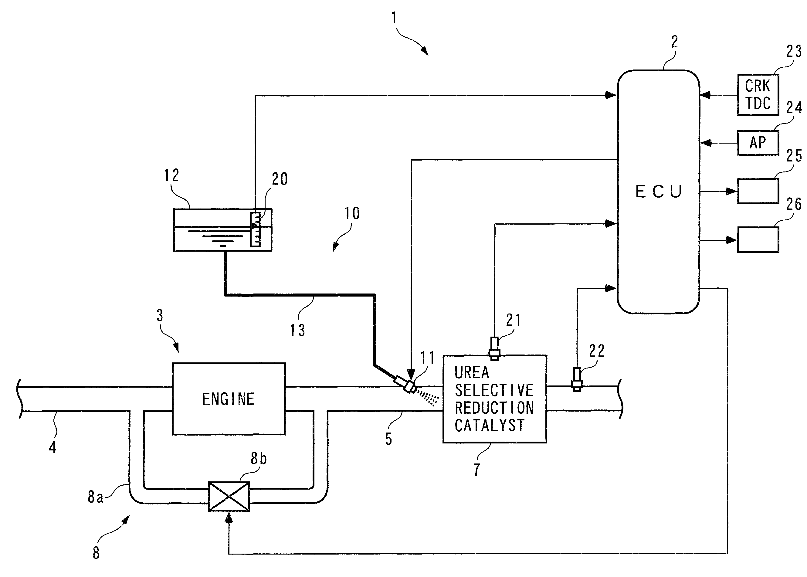
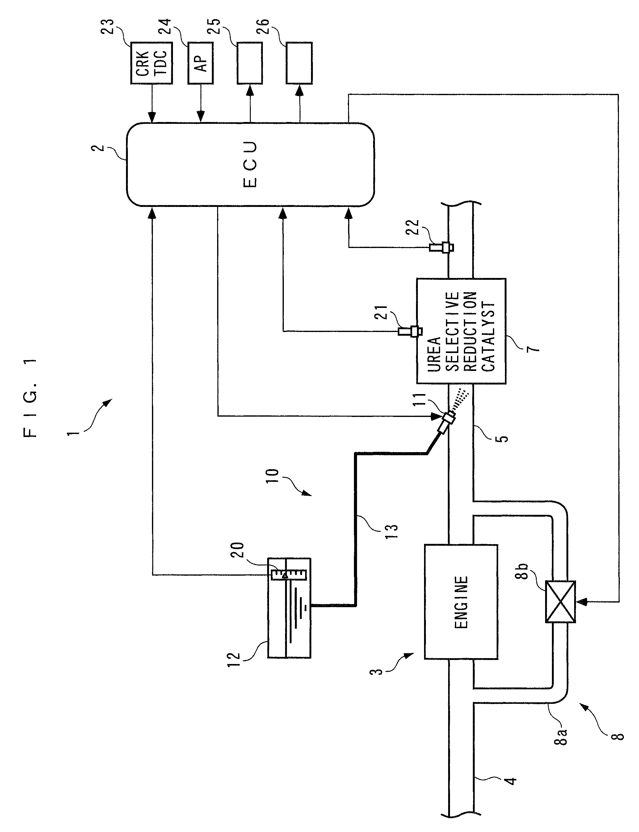
[0066]Hereafter, an exhaust emission control device for an internal combustion engine, according to an embodiment of the present invention will be described with reference to the drawings. FIG. 1 schematically shows the arrangement of the exhaust emission control device 1 according to the present embodiment, and the internal combustion engine (hereinafter referred to as “the engine”) 3 to which is applied the exhaust emission control device. The engine 3 is (a gasoline engine or a diesel engine) of a lean-burn operation type, and is installed on a vehicle, not shown.

[0067]As shown in FIG. 1, the exhaust emission control device 1 is comprised of an ECU 2, a urea selective reduction catalyst 7 disposed in an exhaust passage 5 of the engine 3, a urea injection device 10 for injecting urea water into the exhaust passage 5 on the upstream side of the urea selective reduction catalyst 7, and so forth.

[0068]The urea injection device 10 (reducing agent supply device) includes a urea injecti...


PUM


Abstract

An exhaust emission control device for an internal combustion engine, capable of supplying a just enough amount of reducing agent to a selective reduction catalyst even when a NOx purification ratio of the catalyst is changed by various causes, thereby enabling a high NOx purification ratio and very low exhaust emissions to be maintained. An ECU calculates a filtered value based on a signal from an exhaust gas concentration sensor, calculates a moving average value of a product of the filtered value and a reference input, calculates a control input such that the moving average value becomes equal to 0, and adds a reference input to the control input to calculate an FB injection amount. The ECU calculates an FF injection amount with a predetermined feedforward control algorithm, and adds the FF injection amount to the FB injection amount, to thereby calculate a urea injection amount.

Description

BACKGROUND OF THE INVENTION[0001]1. Field of the Invention[0002]The present invention relates to an exhaust emission control device for an internal combustion engine, for purifying NOx in exhaust gases flowing through an exhaust passage, by a selective reduction catalyst in the presence of a reducing agent.[0003]2. Description of the Related Art[0004]Conventionally, as an exhaust emission control device of this kind, one disclosed in Japanese Laid-Open Patent Publication (Kokai) No. 2004-100700 is known. This internal combustion engine is a diesel engine having an exhaust passage, a reducing agent injection valve, an oxidation catalyst, and a selective reduction catalyst are arranged in the exhaust passage in this order from the upstream side to the downstream side. The reducing agent injection valve injects any of urea, ammonia, and diesel fuel as a reducing agent, whereby NOx in exhaust gases is selectively reduced by the selective reduction catalyst in the presence of a reducing ...

Claims


Application Information

Patent Timeline
Patent Type & Authority Patents(United States)
IPC IPC(8): F01N3/00F01N3/10
CPCF01N3/208F01N9/00F01N11/00F01N9/005F01N2550/02F01N2560/021F01N2560/026F01N2610/02F01N2900/0404F01N2900/0408F01N2900/0411F01N2900/0412F01N2900/1402F01N2900/1602F01N2900/1621F01N2900/1814Y02T10/47Y02T10/24Y02T10/12Y02T10/40
Inventor YASUI, YUJIKAWASUMI, IKUE
Owner HONDA MOTOR CO LTD
Why Eureka
Try Eureka