
Narrow correlator technique for multipath mitigation

a correlator and narrow-band technology, applied in the direction of amplitude demodulation, digital transmission, electrical equipment, etc., can solve the problems of introducing errors in the estimated position of the receiver, estimating the pseudo-range of often contains additional errors, and calculating inaccurate pseudo-ranges. to achieve the effect of mitigating multi-path errors

Inactive Publication Date: 2011-08-16
CSR TECH HLDG
View PDF15 Cites 6 Cited by
  • Summary
  • Abstract
  • Description
  • Claims
  • Application Information

AI Technical Summary

Benefits of technology

"The present invention provides systems and methods for implementing narrowly spaced correlators to mitigate multipath error and adaptively changing the correlator spacing for varying multipath conditions. The invention achieves much narrower correlators spacing than conventional techniques and can adjust the correlator spacing for varying multipath conditions. The technical effects of the invention include improved signal quality and more accurate signal processing."

Problems solved by technology

Additional frequency variation may result due to local oscillator instability.
The estimate of the pseudo-range often contains additional errors due to multi-path, i.e., the reflections of the signals by many objects such as buildings, mountains, etc., as the signals propagate from the satellite to the receiver.
This reception of both line-of-sight and reflected signals often results in the computation of inaccurate pseudo-range, and thus also introduces errors in the estimated position of the receiver.
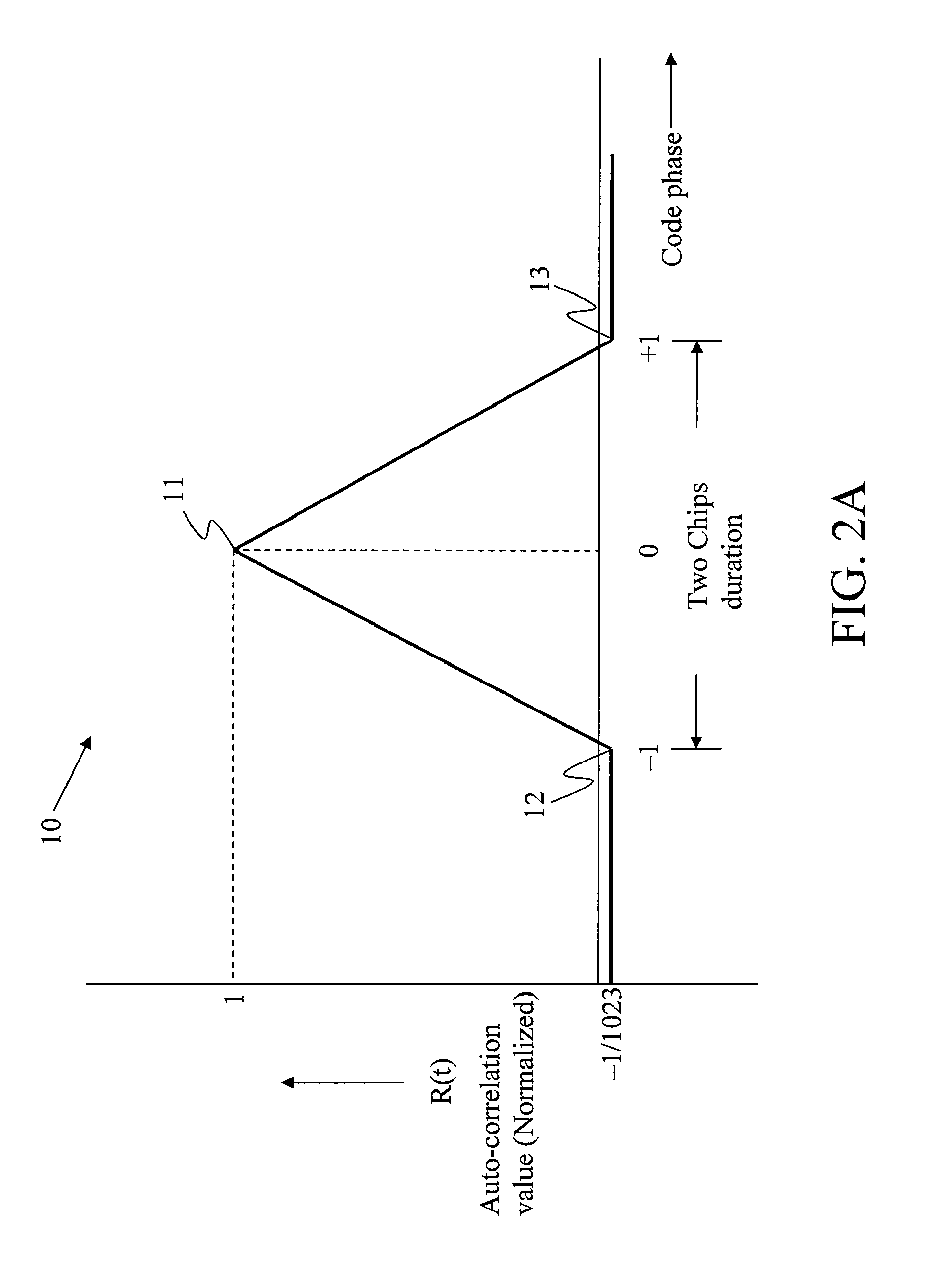
This shift in the position of the correlation peak results in pseudo-range error and error in the computed receiver position.
This reception scenario may be more complex in the presence of a plurality of reflected signals.
Another paper “A practical Approach to the reduction of Pseudorange Multipath errors in L1 GPS receiver” by B. R. Townsend et. al. presented in ION GPS-94, Sep. 20-23, 1994 illustrates a method of multipath mitigation but this method requires a lot of computational power.
The use of narrow correlators, however, increases the hardware complexity and power consumption.
However, most of these methods may not provide good multi-path mitigation below a certain value of multi-path length or in some other cases may involve a lot of computation.
However, this technique requires lot of storage memory and also the comparison may not hold good under all conditions.
However, this approach requires a lot of computation and associated hardware.
This technique uses five correlators but has the disadvantage that it requires a high precision measurement of E2, E1, L1 and L2 values because the measured differences (E1−L1) and (E2−L2) are usually very small.
However, providing a large number of correlators results in increased gate count in the hardware, which increases the power and the physical size.
Further, it is not possible using these methods to adaptively change the correlator spacing as may be required in varying multipath conditions.

Method used


Image

  • Narrow correlator technique for multipath mitigation
  • Narrow correlator technique for multipath mitigation
  • Narrow correlator technique for multipath mitigation

Examples


first embodiment

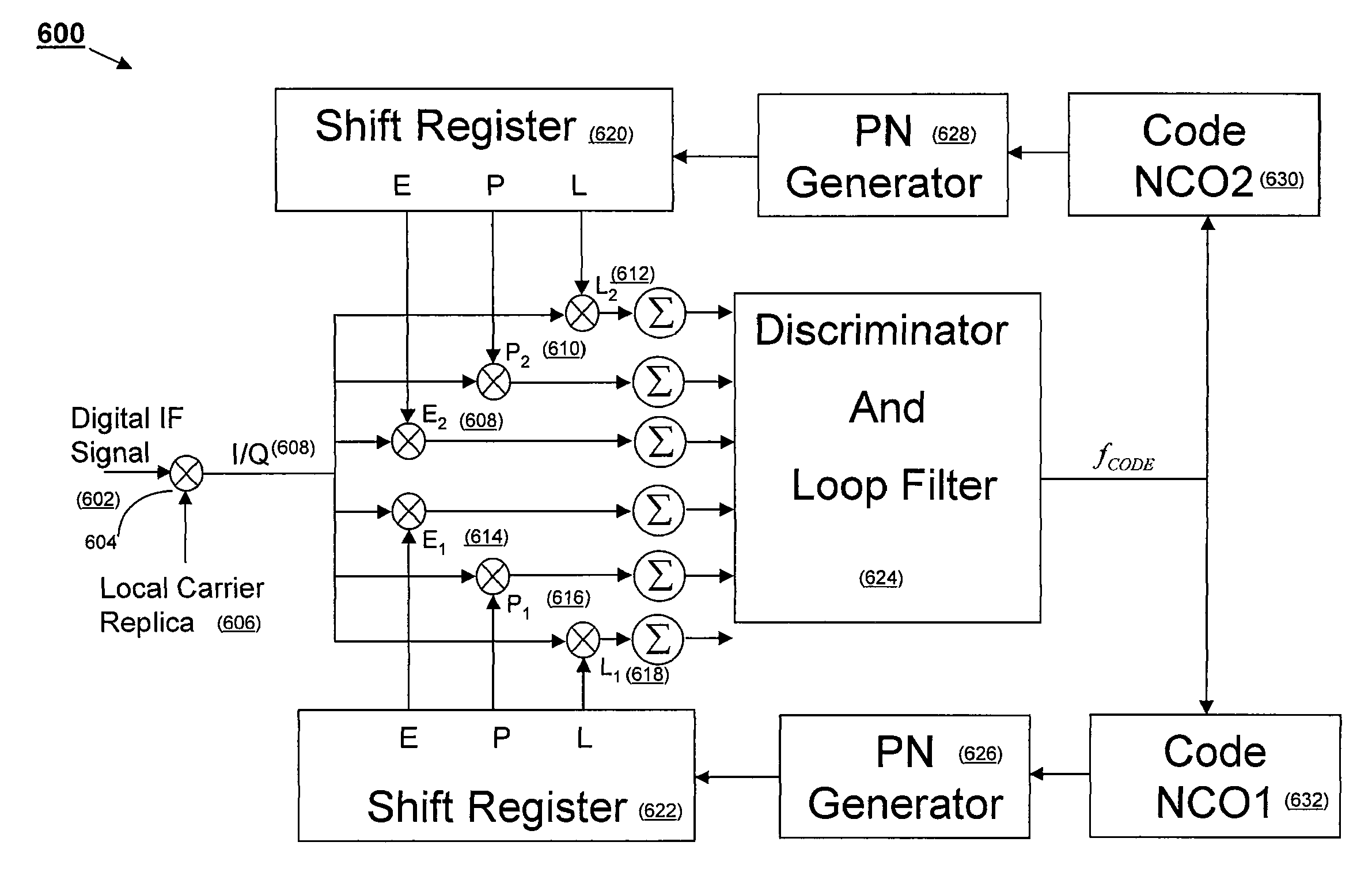
[0038]The first embodiment is based on a direct implementation. In this method one hardware correlator set can be used to implement both correlator sets. This may be done by having one hardware correlator set operate twice on the same set of stored signal samples at the same code frequency but different code phases to implement both correlator sets. This requires the correlator set to run fast enough to accommodate both sets in one hardware set. The signal samples may be read from the FIFO memory mentioned earlier. While the P1 and P2 provide narrow correlation space, the E1, E2 and L1, L2 provide correlation values for wider correlation space. This is useful to guard against large code delay error, which occurs when the peak is far away from the P1 and P2. In this case, the values of E1, E2 and L1, L2 can be used to find the peak.

second embodiment

[0039]implementation is based on time-sharing of the correlators. In this method, if the correlators can not run fast enough, a time division approach can be used. In one embodiment, one hardware correlator set is used by having the correlator set alternately implement the E1, P1 and L1 set and the E2, P2 and L2 set. For example, the correlator set may implement the E1, P1 and L1 set during odd milliseconds and the E2, P2 and L2 set used during even milliseconds. In this embodiment, the NCO code phase value is suitably updated, e.g., by adding or subtracting a code phase value corresponding to the desired correlator spacing between implementations. Overflow and underflow problems may also need to be taken care of in both methods, which occurs when the result of a code phase adjustment is larger or smaller than the range that the code NCO can represent.

[0040]In an embodiment, a computation of error due to the multipath may be done by determining the profile of the correlation and usi...


PUM


Abstract

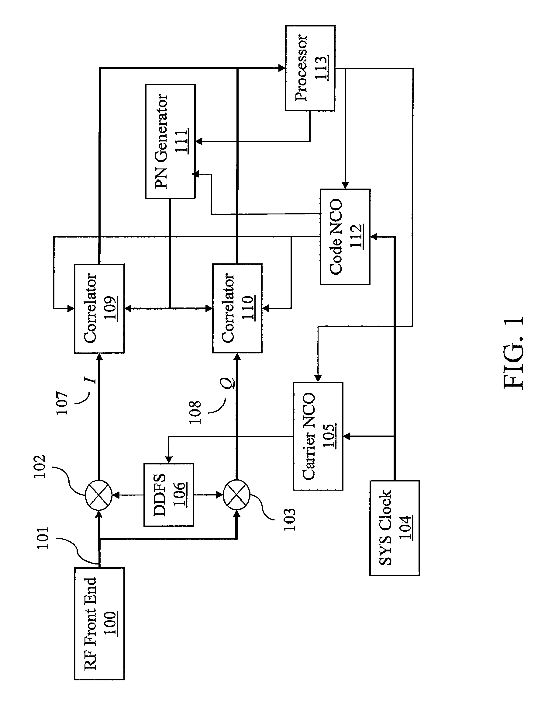
The present invention provides systems and methods for implementing narrowly spaced correlators to mitigate multipath error, and systems and methods for adaptively changing the correlator spacing for varying multipath conditions. In an embodiment, two sets of correlators with the same code frequency but different code phases are used to implement an adjustable correlator spacing. The correlator spacing is determined by the code phase difference between the two sets of correlators, which can be adjusted, e.g., by adjusting the code phase values of Numerically Controlled Oscillators (NCOs). An advantage of embodiments of the present invention is that they can achieve much narrower correlator spacings than conventional techniques, e.g., by making the code phase difference between the two sets of correlators very small. Further, the correlator spacing can be adjusted for varying multipath conditions, whereas the correlator spacing in conventional techniques is fixed.

Description

FIELD OF THE INVENTION[0001]The present invention relates generally to navigation and spread spectrum signal receivers, and more particularly, to systems and methods for mitigating multipath error based on adjustable correlator spacing implemented in software, hardware, or both.BACKGROUND OF THE INVENTION[0002]The global positioning system (GPS) is a satellite-based radio-navigation system built and operated by the United States Department of Defense. The system uses twenty-four satellites orbiting the earth at an altitude of about 11,000 miles with a period of about twelve hours. Some additional satellites may be present as spares. These satellites are placed in six different orbits such that at any time a minimum of six satellites are visible at any location on the surface of the earth except in the polar region. Each satellite transmits a time and position signal referenced to an atomic clock. A typical GPS receiver locks onto this signal and extracts the data contained in it. Us...

Claims


Application Information

Patent Timeline
Patent Type & Authority Patents(United States)
IPC IPC(8): H04B1/00H04L27/06
CPCH04B1/7085H04B1/709H04B2201/70715
Inventor MO, JUNHAN, SHAOWEI
Owner CSR TECH HLDG
Learn More