
Wavelet transformation device and method, wavelet inverse transformation device and method, program, and recording medium for performing wavelet transformation at a plurality of division levels

a wavelet transformation and wavelet technology, applied in the field of wavelet wavelet inverse transformation devices and methods, programs, and recording media, can solve the problems of increasing power consumption, inability to obtain sufficient bandwidth, and difficulty in performing wavelet transformation at high speeds

Inactive Publication Date: 2011-08-16
SONY CORP
View PDF15 Cites 2 Cited by
  • Summary
  • Abstract
  • Description
  • Claims
  • Application Information

AI Technical Summary

Benefits of technology

Enables high-speed wavelet transformation and inverse transformation without the need for external memory, reducing power consumption and simplifying hardware design, while maintaining high processing efficiency for image signals.

Problems solved by technology

However, techniques wherein frequency coefficients are written out to external memory and read in again have the problem than sufficient bandwidth cannot be obtained since data is exchanged between the external memory an wavelet transformation unit, so it has been difficult to perform wavelet transformation at high speeds.
Also, raising the clock (operating frequency) is effective in increasing the speed of data between the external memory and wavelet transformation unit, but simple increasing of the clock not only results in the problem of increased power consumption; this is not readily handled by hardware such as FPGA (Field Programmable Gate Array) and PLD (Programmable Logic Device).

Method used


Image

  • Wavelet transformation device and method, wavelet inverse transformation device and method, program, and recording medium for performing wavelet transformation at a plurality of division levels
  • Wavelet transformation device and method, wavelet inverse transformation device and method, program, and recording medium for performing wavelet transformation at a plurality of division levels
  • Wavelet transformation device and method, wavelet inverse transformation device and method, program, and recording medium for performing wavelet transformation at a plurality of division levels

Examples


Embodiment Construction

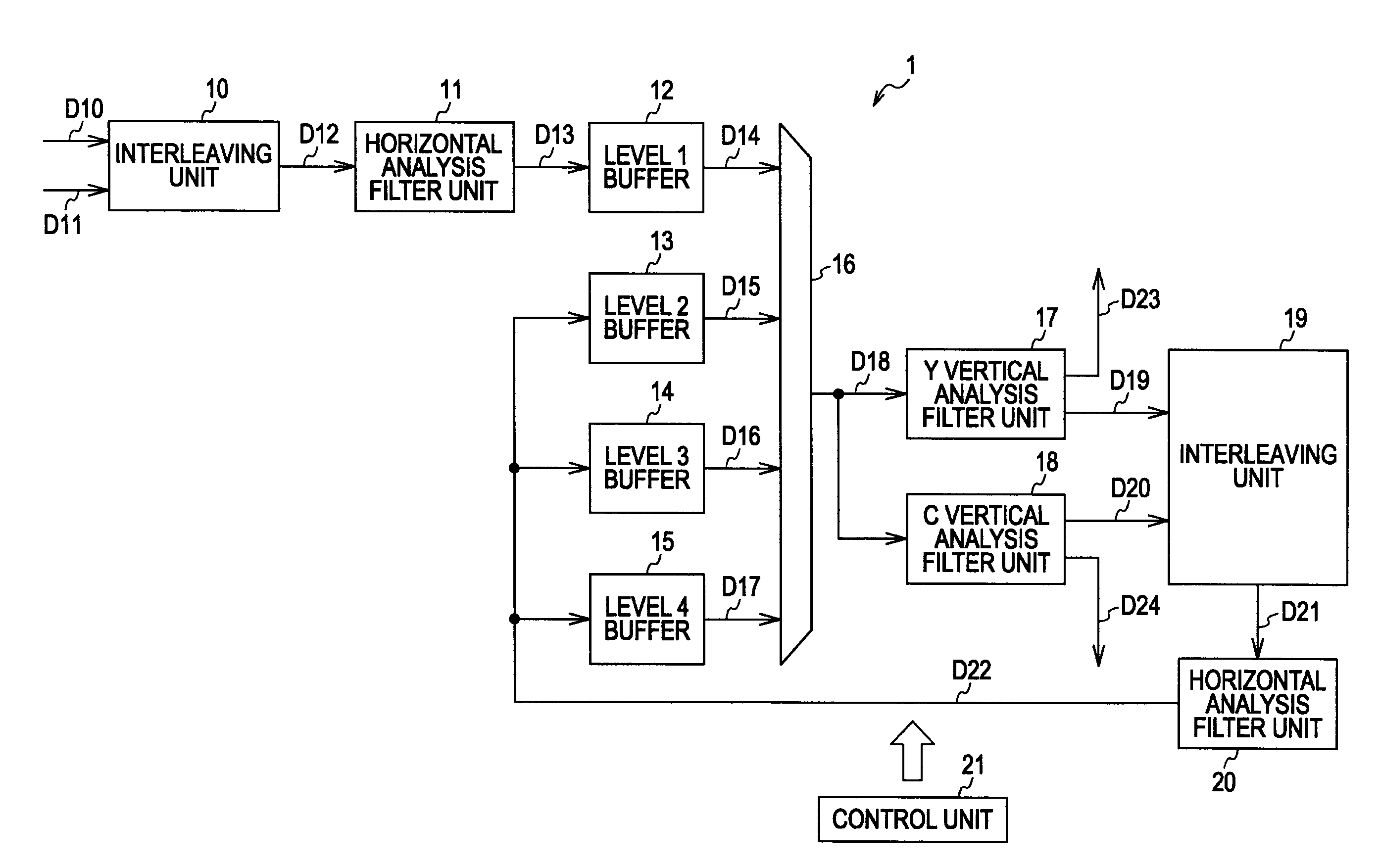
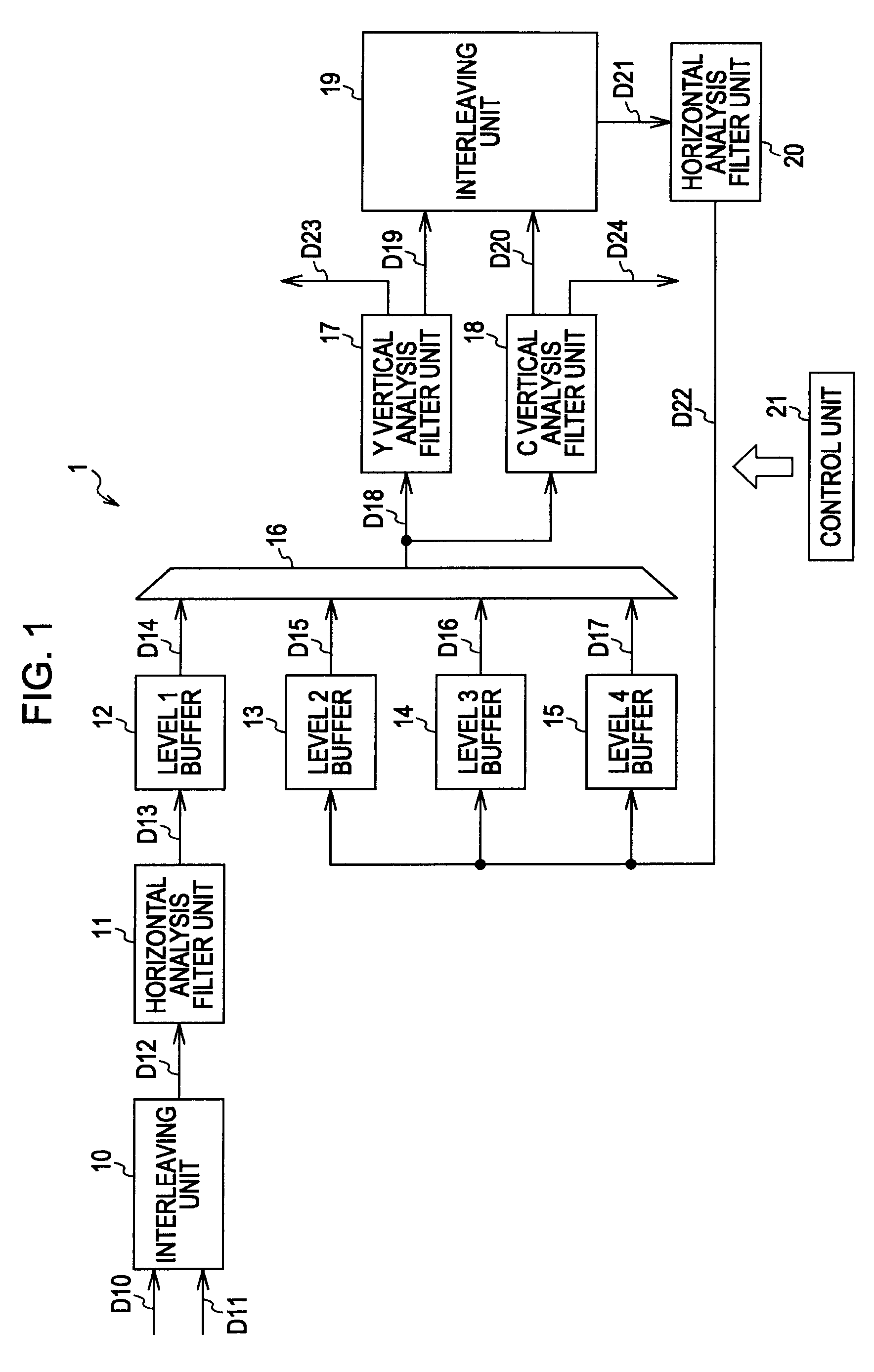
[0070]FIG. 1 is a diagram illustrating a configuration example of an embodiment of a wavelet transformation device to which an embodiment of the present invention has been applied. The wavelet transformation device 1 is a band analysis device which takes image data as input, and performs horizontal direction filtering and vertical direction filtering, in which lowband components are hierarchically divided to a predetermined division level (in the example shown in FIG. 1, to division level 4).

[0071]The wavelet transformation device 1 shown in FIG. 1 is configured of an interleaving unit 10, a horizontal analysis filter unit 11, level 1 buffer 12, level 2 buffer 13, level 3 buffer 14, level 4 buffer 15, selector 16, Y (brightness) vertical analysis filter unit 17, C (color difference) vertical analysis filter unit 18, interleaving unit 19, horizontal analysis filter unit 20, and control unit 21.

[0072]Brightness signals (brightness components signals) D10 and color different signals (c...


PUM


Abstract

A wavelet transformation device for performing wavelet transformation at a plurality of division levels as to image signals. A horizontal filtering unit subjects the image signals to horizontal direction lowband analysis filtering and highband analysis filtering. Buffers which are independent for each of the division levels, hold frequency components, which are generated as the results of the horizontal direction analysis filtering by the horizontal filtering unit, for each of the division levels. Interleaving devices comprising at least one interleaving unit interleaving brightness components and color difference components of the image signals and interleaving highband components and lowband components of buffered filter results.

Description

CROSS REFERENCES TO RELATED APPLICATIONS[0001]The present invention contains subject matter related to Japanese Patent Application No. 2006-193669 filed in the Japanese Patent Office on Jul. 14, 2006, the entire contents of which are incorporated herein by reference.BACKGROUND OF THE INVENTION[0002]1. Field of the Invention[0003]The present invention relates to a wavelet transformation device and method, a wavelet inverse transformation device and method, a program, and a recording medium, and more particularly relates to a wavelet transformation device and method, a wavelet inverse transformation device and method, a program, and a recording medium, enabling high-speed wavelet transformation to be performed by exchanging data with internal memory.[0004]2. Description of the Related Art[0005]An image compression method representative of known methods is the JPEG (Joint Photographic Experts Group) method that has been standardized by the ISO (International Standards Organization). Th...

Claims


Application Information

Patent Timeline
Patent Type & Authority Patents(United States)
IPC IPC(8): G06K9/46H03M7/30H04N1/41H04N19/00H04N19/423H04N19/635H04N19/70H04N19/80H04N19/91
CPCH04N19/63
Inventor FUKUHARA, TAKAHIROANDO, KATSUTOSHINISHIMURA, NAOTOTANAKA, YUUKI
Owner SONY CORP
Learn More