Airloop window wall system

a technology of air loops and window walls, applied in the field of exterior wall systems, can solve the problems of inability time-consuming process to achieve the required quality, and gross insufficient durability of the perfect sealing property at the critical sealing locations, etc., and achieve the effect of completely impractical field execution without pre-engineering calculation

Inactive Publication Date: 2011-08-23
ADVANCED BUILDING SYST
View PDF13 Cites 25 Cited by
  • Summary
  • Abstract
  • Description
  • Claims
  • Application Information

AI Technical Summary

Benefits of technology

[0012]1. To provide a window wall system with durable water-tightness performance.
[0013]2. To provide a window wall system to tolerate high degree of building construction tolerance with easy tolerance adjustment and without impairing the structural integrity of the anchoring system.

Problems solved by technology

In addition, the ability to maintain a curtain wall type of flush exterior appearance is highly desirable but rather difficult since the window wall must be supported on the floor while the water infiltrated into the wall panel joints must be drained to the exterior of the slab edge making it become necessary for the slab edge cover to be protruded from the face of the window wall.
Experience indicated that the durability of the perfect sealing property at the critical seal locations is grossly inadequate due to workmanship and material degradation problems as well as stress fatigue due to various structural movements.(2) The erected window wall is expected to be plumb and leveled at the design position.
In both steps of the screw application, the anchoring member is very easy to slide on top of the shims causing it to be out of position and the shims are very easy to shift out of position, therefore, it is a very time consuming process to achieve the required quality result.
Even though a reduced screw strength can be theoretically compensated by a reduced screw spacing at the high shim locations, it can't be shown on the drawing since the high shim locations can't be predefined and it is totally impractical to execute in the field without a pre-engineering calculation.
It is most likely to compromise the structural integrity of the erected window wall.
Even though the required screw spacing can be conservatively engineered with the assumption of highest shim condition, it would significantly increase the cost.(3) In a conventional window wall system, each panel has a male jamb member and a female jamb member.
Due to the directional erection requirement, project delays are commonly caused by inadequate coordination with other trades on the job.(4) In a conventional window wall system, the exterior floor slab edge cover and some exterior perimeter caulking lines are normally applied from outside after the panel erection.
Experiences indicated multiple difficulties with anchoring and construction tolerance problems due to the notched mullion with discrete anchoring locations.

Method used


Image

  • Airloop window wall system
  • Airloop window wall system
  • Airloop window wall system

Examples


Embodiment Construction

[0025]Reference will now be made in detail to the preferred embodiments of the present invention, examples of which are illustrated in the accompanying drawings. Wherever possible, the same reference numbers are used in the drawings and the description to refer to the same or like parts.

[0026]In order to better explain the working principles of the invention, the following terminology will be used herein:

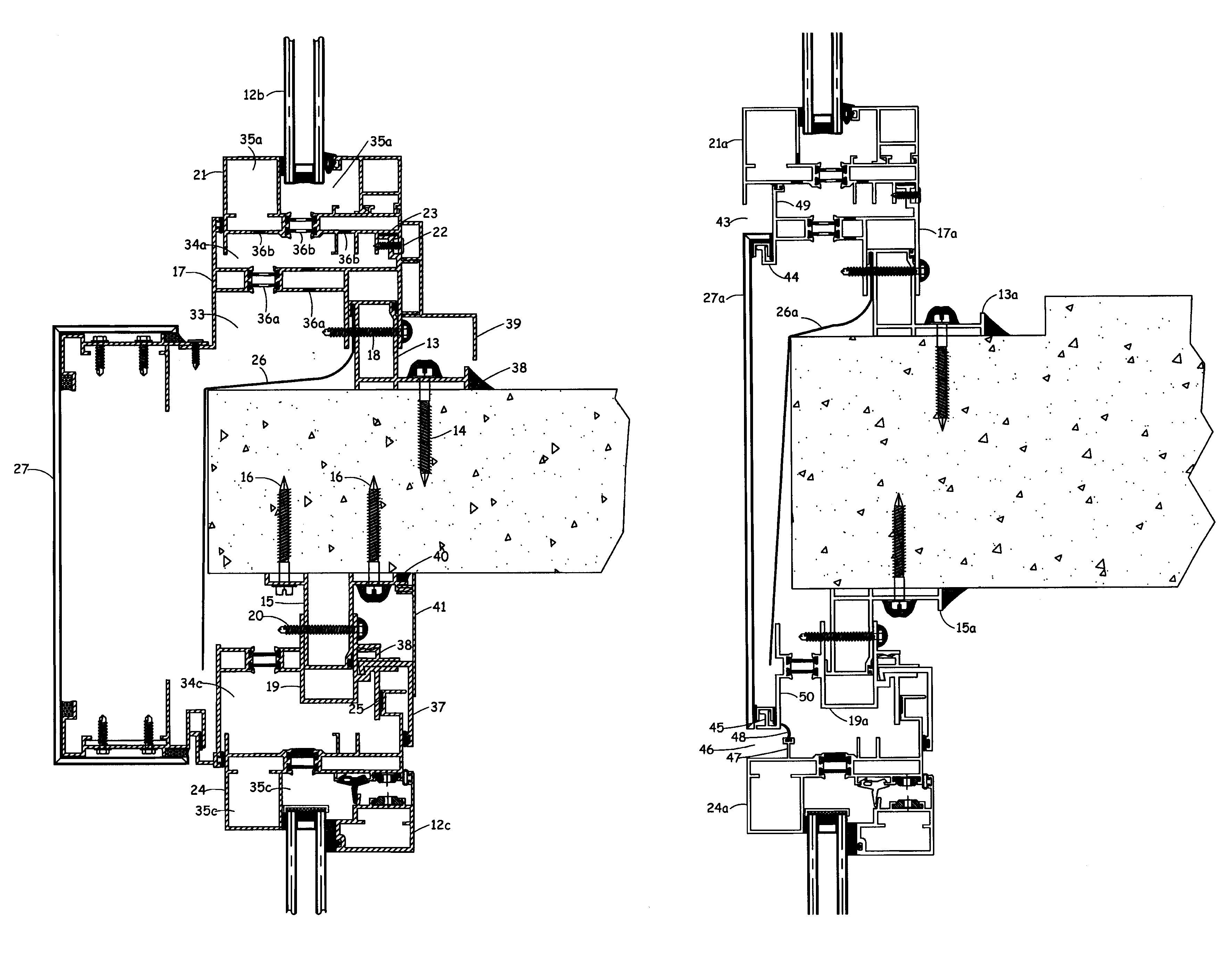
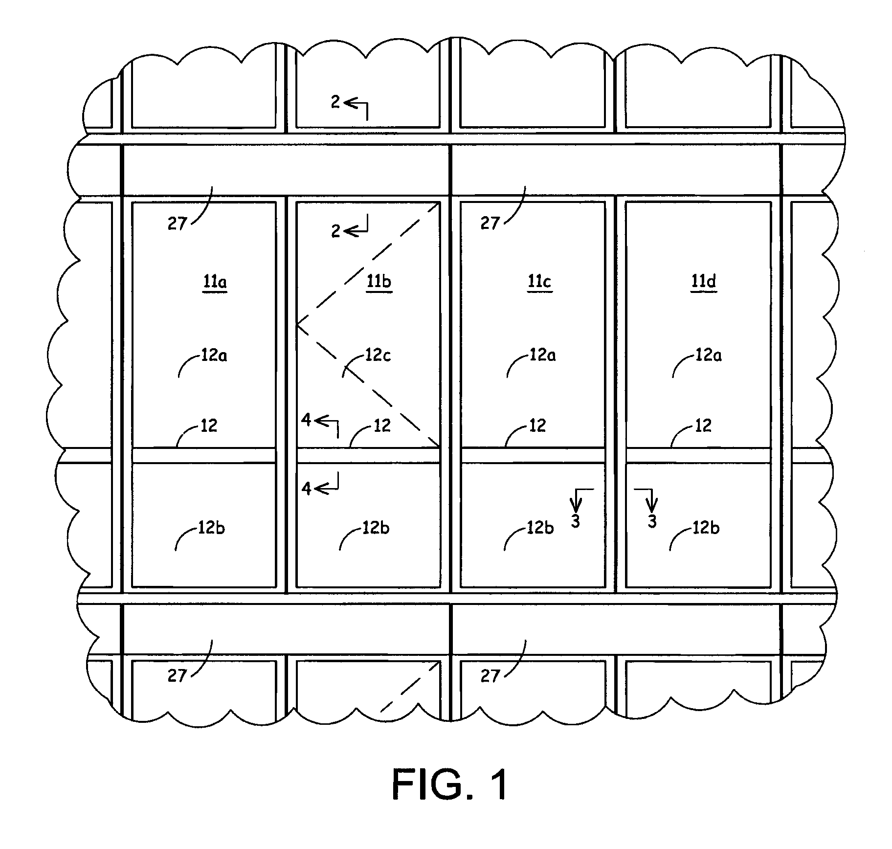
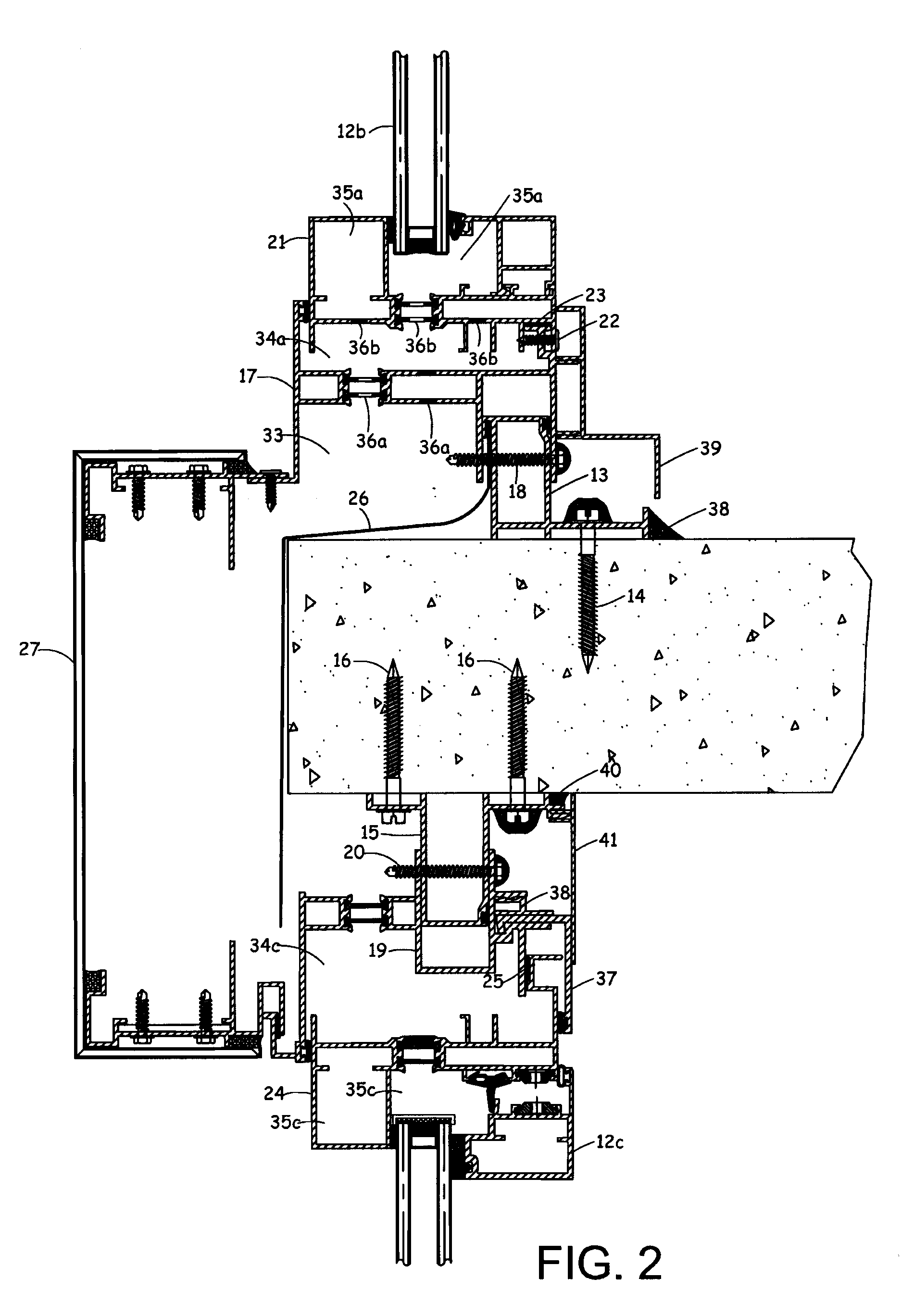
[0027]Window Wall Panel: one of a plurality of panels or panel assemblies having at least one building facing wall element secured and nominally sealed to a panel frame, typically a perimeter portion of the facing element is shop secured and sealed to segments of the panel frame;

[0028]Inner Airloop: an air space substantially forming a loop around and near the perimeter edges of the facing elements and generally within the panel frame; and

[0029]Outer Airloop: an air space substantially forming a loop around and outside of the panel frame.

[0030]For clarity the following list of numer...


PUM


Abstract

An airloop wall system with durable water-tightness performance is disclosed. The system comprises a base anchor member secured to a top surface of a first floor slab, a base track connected to the base anchor, a base flashing for repelling moisture, a first ceiling anchor member secured to a bottom surface of the first floor slab, a first ceiling track connected to the first ceiling anchor member, a slab edge panel attached to the base track and the first ceiling track, a second ceiling anchor member secured to a bottom surface of a second floor slab, a second ceiling track connected to the second ceiling anchor member, a panel sill frame attached to the base track, a panel head frame attached to the second ceiling track, two jamb frames, and a panel secured between the frames. Corners of the frames are miter-matched such that air spaces inside form an airloop.

Description

REFERENCE TO RELATED APPLICATIONS[0001]This Utility Patent Application is based on Provisional Patent Application Ser. No. 61 / 028,042 filed 12 Feb. 2008, and Provisional Patent Application Ser. No. 61 / 044,815, filed 14 Apr. 2008.FIELD OF THE INVENTION[0002]This invention relates to exterior wall systems inserted between two adjacent floors known as window wall, specifically an improvement on the performances of the wall systems by the application of Airloop Principle as described by Ting in U.S. Pat. Nos. 5,452,552 and 5,598,671. The structure disclosed in U.S. Pat. No. 5,452,552 is also known as an exposed frame Airloop curtain wall system and the structure disclosed in U.S. Pat. No. 5,598,671 is also known as a hidden frame Airloop curtain wall system.BACKGROUND OF THE INVENTION[0003]A window wall system which in general, spans from the top surface of a floor to the underside of the floor above or to the bottom edge of a spandrel masonry or concrete panel above. Most of the window...

Claims


Application Information

Patent Timeline
Patent Type & Authority Patents(United States)
IPC IPC(8): E06B7/02E06B7/10E04H1/00
CPCE04B2/90
Inventor TING, RAYMOND M. L.
Owner ADVANCED BUILDING SYST
Why Eureka
Try Eureka