Continuous positive airway supply system to nasal cannula

Active Publication Date: 2011-08-23
NEOTECH PROD LLC
View PDF0 Cites 6 Cited by
  • Summary
  • Abstract
  • Description
  • Claims
  • Application Information

AI Technical Summary

Benefits of technology

[0018]Another object of the present invention is to provide for requisite warmth and humidification of the air stream. The complications of inadvertent pressure propagation are avoided. NCPAP

Problems solved by technology

Difficulty in regulation of pressure, and concerns regarding the damaging effects of inadequately warmed and humidified oxygen delivery systems on nasal mucosa, precluded the use of these devices in the more acute phases of respiratory distress and at the higher liter flow rates that would have been required to generate the pressures necessary to provide for that particular disease process.
Certain devices held the promise of improved humidific

Method used


Image

  • Continuous positive airway supply system to nasal cannula
  • Continuous positive airway supply system to nasal cannula
  • Continuous positive airway supply system to nasal cannula

Examples


Embodiment Construction

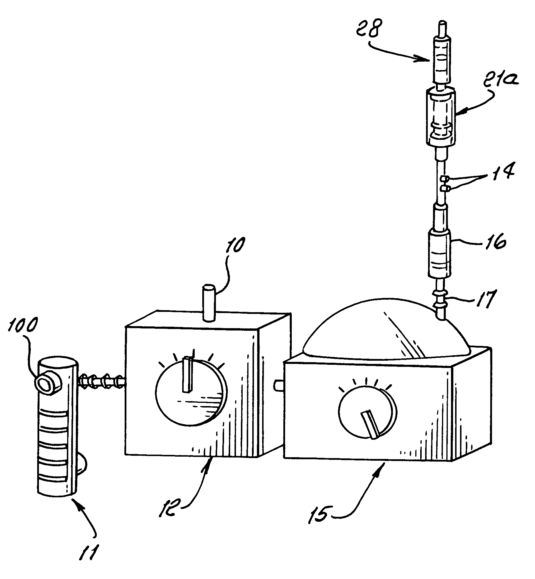
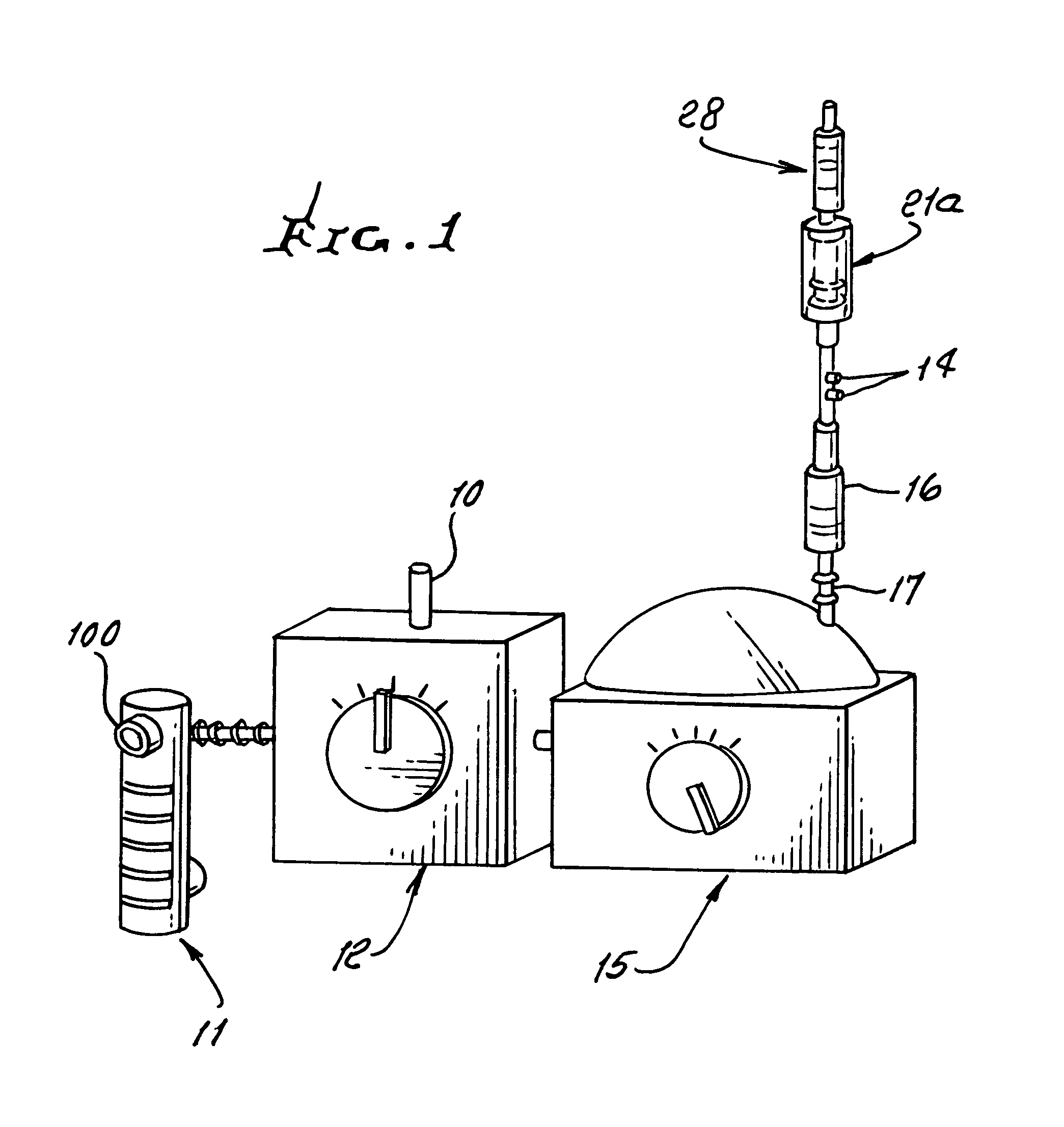
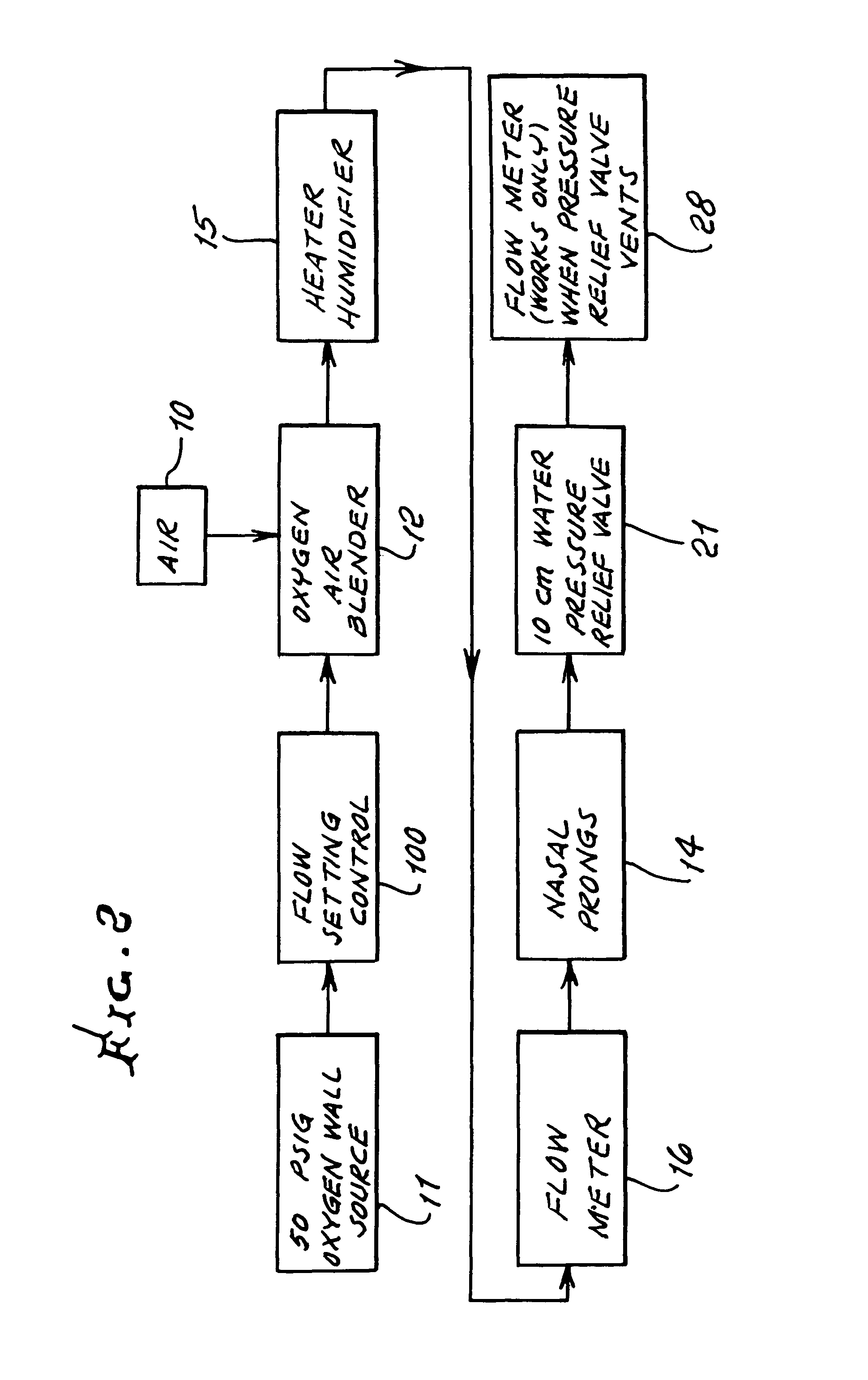
[0027]Referring first to FIG. 1, showing a preferred system, air supplied at 10, and oxygen supplied at 100 enter a blending zone 12, to be thoroughly mixed or blended. A control 11 to increase or decrease flows from the oxygen supply 100 is shown. The flowing mix passes to a flow meter at 16 via a warmer / humidifier 15, which may consist of warm water into which the flow is injected to bubble up and continue flowing as at 17, as warmed, humidified air / oxygen blend. Some of the flow passes to the small tubes or prongs 14 for supply to the infant's lungs. Some of that supply may variably leak to atmosphere, via the nostrils or expelled via the infant's mouth, for example along with flow expelled from the lungs, during breathing. Flow pressure supplied to the cannula is desirably below about 10 cm water pressure. The oxygen supply, as at hospital wall outlet 100, is typically about 50 psi (3,154 cm / H20).

[0028]Remnant air passes in duct 20FIG. 4 to an outlet, such as a “pop-off” valve. ...


PUM


Abstract

The invention concerns a combination control for use in nasal cannula therapy, and includes a high flow, nasal cannula respiratory assistance ducted system.

Description

[0001]This regular application is based on provisional application No. 60 / 850,410, filed Oct. 10, 2006.BACKGROUND OF THE INVENTION[0002]This invention relates generally to nasal cannula therapy, and more particularly to improvements concerning fluid flow in nasal cannula therapy systems.[0003]Nasal continuous positive airway pressure, NCPAP, is a used standard for administration of non-invasive positive airway pressure in the Neonate. Historically, Nasal Cannulae have been used at low flow rates (<1.5 1 pm) during infant weaning from assisted ventilation, or for maintenance in the sub-acute phase of chronic lung disease. Difficulty in regulation of pressure, and concerns regarding the damaging effects of inadequately warmed and humidified oxygen delivery systems on nasal mucosa, precluded the use of these devices in the more acute phases of respiratory distress and at the higher liter flow rates that would have been required to generate the pressures necessary to provide for that...

Claims


Application Information

Patent Timeline
IPC IPC(8): A61M11/00
CPCA61M16/0666A61M16/12A61M16/109A61M16/209A61M16/16A61M2016/003A61M2202/0208A61M2202/0275A61M2205/3653
Inventor GOLDSTEIN, MITCHELLHEYMAN, ARNOLD M.
Owner NEOTECH PROD LLC
Why Eureka
Try Eureka