
Dual flywheel axially compact epicyclical drive

a technology of axial compactness and flywheel, applied in the direction of shafts, bearings, agriculture tools and machines, etc., can solve the problems of increasing the possibility of unavoidably pushing over adjacent standing crops, increasing weight, cost and complexity, and counterbalance correspondingly increasing, so as to reduce vibrational output, reduce eccentric and torsional loading conditions, and reduce failures.

Active Publication Date: 2011-09-06
BLUE LEAF I P INC
View PDF39 Cites 78 Cited by
  • Summary
  • Abstract
  • Description
  • Claims
  • Application Information

AI Technical Summary

Benefits of technology

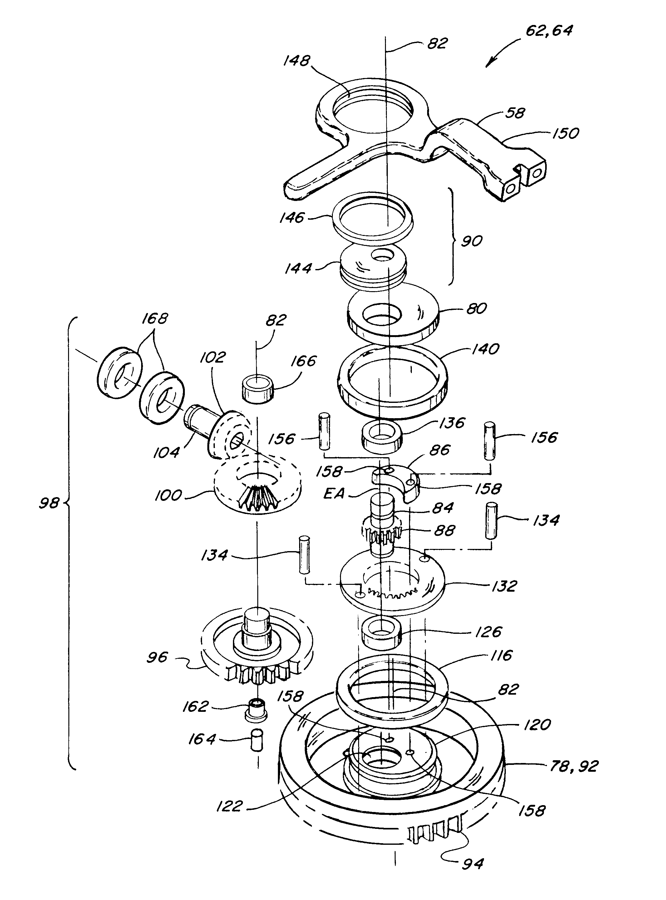
[0017]As an advantage of the invention, the dual flywheel and pinion assembly substantially eliminates eccentric and torsional loading conditions emanating from the internal mechanism of the drive to the header, and the vibrations and damage that can result. This feature, when combined with the use of dual drives timed to oppositely reciprocate the knife assemblies of the sickle, provides a greatly reduced vibrational output overall for smoother operation and reduced failure. In this regard, the dual flywheels are preferably connected together for joint rotation, e.g., using pinned connections, preferably through the counterweight, which enables side and torsional loads to be transferred or distributed through and between the flywheels, to reduce load concentrations on the flywheels individually and on the pinion. For instance, at least a portion of the drive forces exerted as side and torsional loads against the driven one of the flywheels are transferred through the connection directly to the other flywheel. And, portions of loads exerted by the reciprocating action of the knife assembly on the more proximal flywheel are transferred to the other flywheel through the connection, such that, overall, the dual flywheel and pinion assembly is robust and resistant to damage.
, the dual flywheel and pinion assembly substantially eliminates eccentric and torsional loading conditions emanating from the internal mechanism of the drive to the header, and the vibrations and damage that can result. This feature, when combined with the use of dual drives timed to oppositely reciprocate the knife assemblies of the sickle, provides a greatly reduced vibrational output overall for smoother operation and reduced failure. In this regard, the dual flywheels are preferably connected together for joint rotation, e.g., using pinned connections, preferably through the counterweight, which enables side and torsional loads to be transferred or distributed through and between the flywheels, to reduce load concentrations on the flywheels individually and on the pinion. For instance, at least a portion of the drive forces exerted as side and torsional loads against the driven one of the flywheels are transferred through the connection directly to the other flywheel. And, portions of loads exerted by the reciprocating action of the knife assembly on the more proximal flywheel are transferred to the other flywheel through the connection, such that, overall, the dual flywheel and pinion assembly is robust and resistant to damage.

Problems solved by technology

Disadvantages of the side location include that the header must include significant frame structure for supporting the drive and to withstand forces and vibrations generated thereby.
The end structure or crop divider at the end of the header must also be relatively wide, to accommodate the drive and to direct adjacent standing crops therepast, and increasing the possibility of unavoidably pushing over adjacent standing crops.
This typically involves relatively long mechanical drive lines connecting the two drives together, which is disadvantageous as it adds weight, cost and complexity.
Additionally, as the weight of the knife assembly is increased, e.g., for a longer sickle, the counterbalance must be correspondingly increased, which increases the fore and aft eccentric loading condition.
These high forces can have at least two negative effects, vibration at and within the drive system that may be transmitted to other components of the machine, and torsional and vibration related failure of the structural components of the drive itself, and also the seals thereof.
To compound the seal failure problem, operation of plant cutting machines typically generates substantial dust and plant fragments that can rapidly damage seals and infiltrate the drive to cause failure thereof.

Method used


Image

  • Dual flywheel axially compact epicyclical drive
  • Dual flywheel axially compact epicyclical drive
  • Dual flywheel axially compact epicyclical drive

Examples


Embodiment Construction

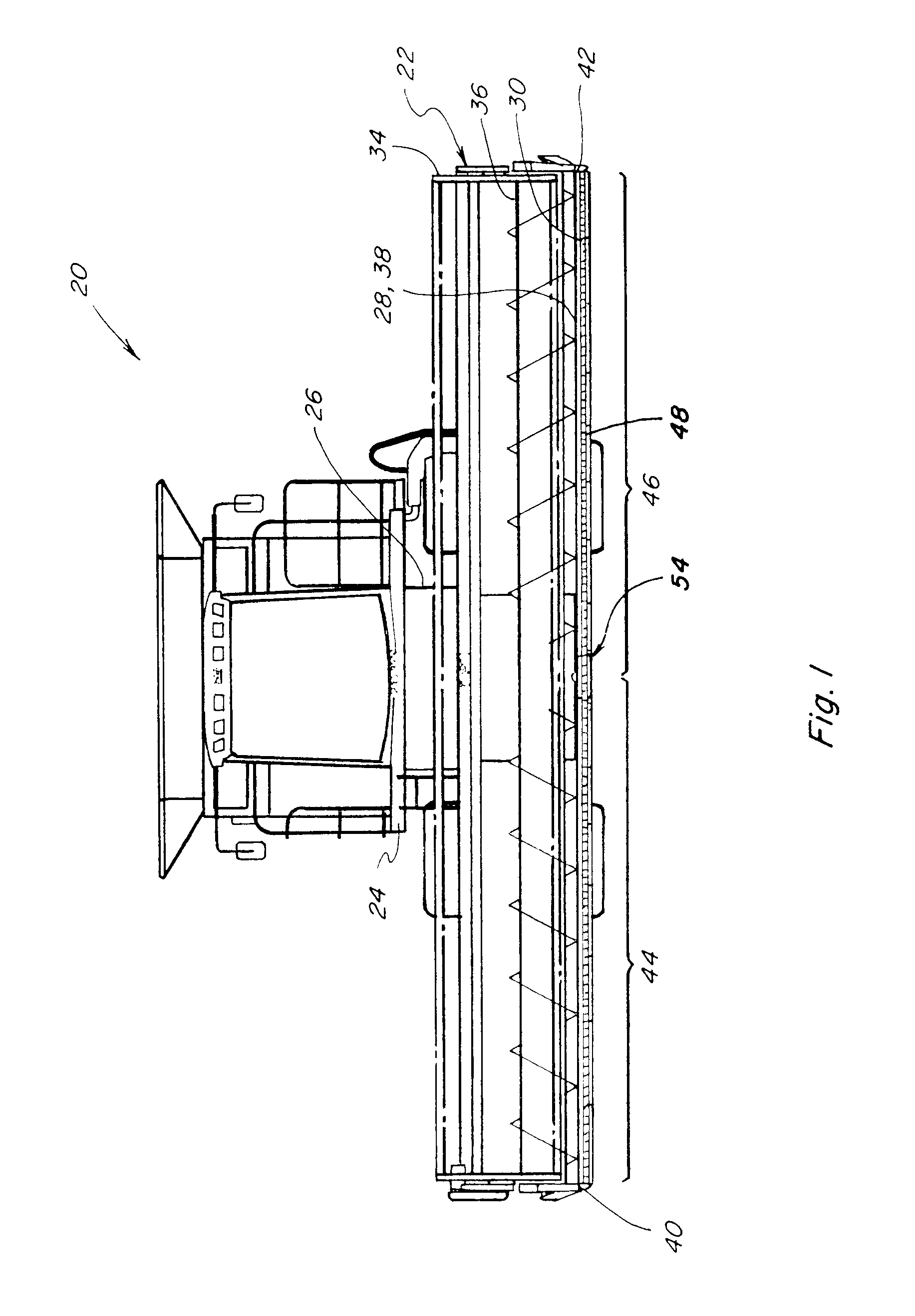
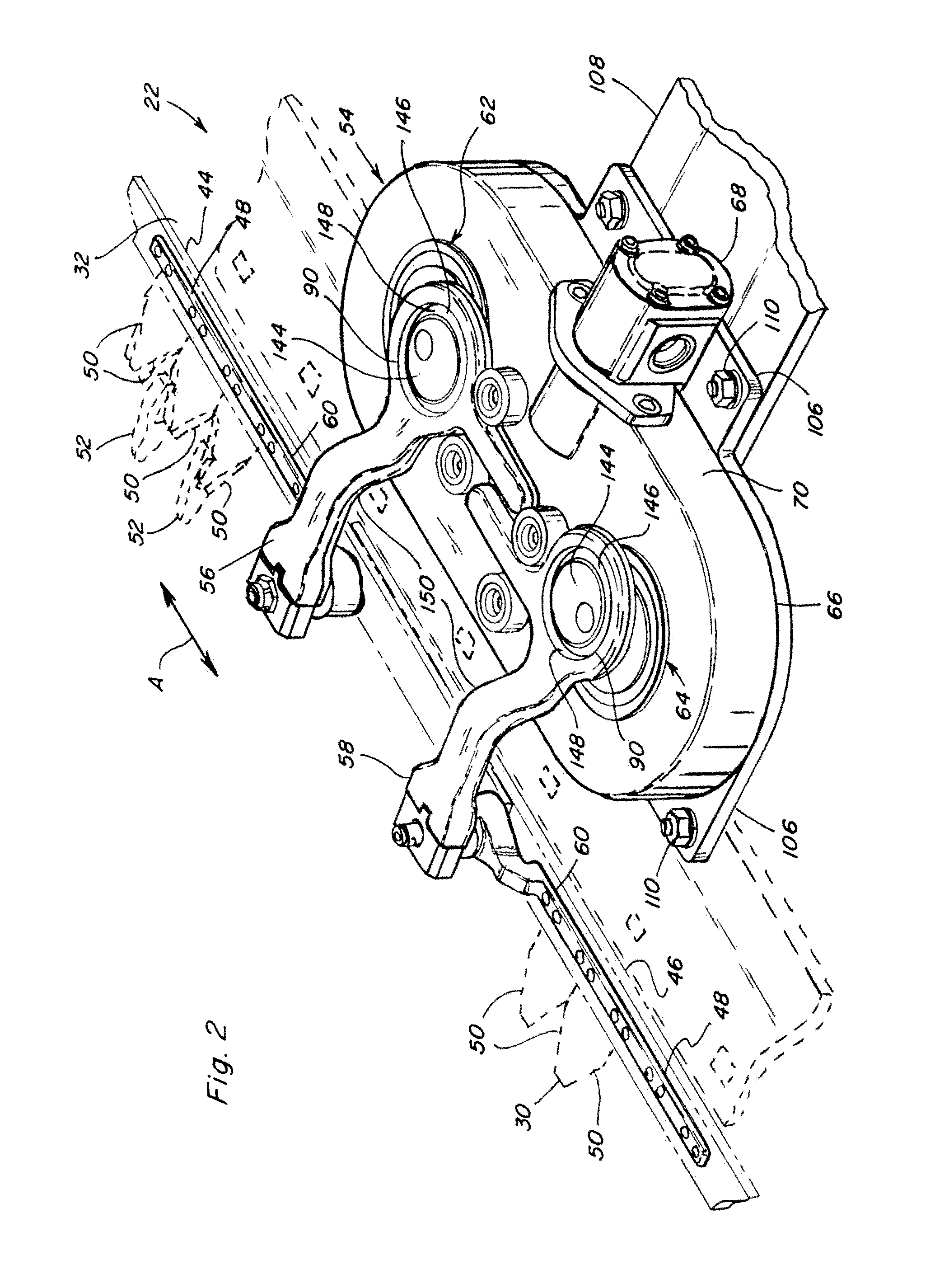
[0031]Turning now to the drawings wherein several preferred embodiments of the invention are shown, in FIG. 1, a conventional, well known agricultural cutting machine, which is a combine 20, is shown including a header 22. Header 22 is shown supported in the conventional, well-known manner on a forward end 24 of combine 20, and is operable for cutting or severing crops such as, but not limited to, small grains such as wheat and soybeans, and inducting the severed crops into a feeder 26 for conveyance into combine 20 for threshing and cleaning, in the well known manner, as combine 20 moves forwardly over a field. Header 22 includes a pan or floor 28 which is supported in desired proximity to the surface of the field during the harvesting operation, and an elongate, sidewardly extending sickle 30 along a forward edge portion 32 of floor 28, sickle 30 being operable for severing the crop for induction into header 22, as will be explained. Header 22 additionally includes an elongate, si...


PUM


Abstract

The epicyclical drive incorporates a dual flywheel carrying a pinion in a balanced axially compact assembly. The assembly includes a counterweight for the pinion nested between the flywheels, which also connects the flywheels and transfers loading conditions therebetween, to reduce and distribute torsional and eccentric loading conditions and reduce vibrations. The use of a second flywheel also provides an improved rotary seal capability for keeping out dust, debris and moisture. The drive is adapted for incorporation into a floor of a header of an agricultural harvesting machine for reciprocatingly driving a sickle thereof, advantageously jointly with a mirror image companion drive in a side by side relationship and timed such that forces generated by the reciprocating actions are cancelled.

Description

TECHNICAL FIELD[0001]This invention relates generally to an epicyclical drive incorporating a dual flywheel and pinion assembly in a counterbalanced axially compact arrangement, which reduces torsional and eccentric loading and vibrations during operation and provides an improved seal, and which is particularly well adapted for incorporation into a floor of a header of an agricultural harvesting machine for driving the sickle thereof.BACKGROUND ART[0002]Epicyclical drives are noted for their utility for converting rotary motion to reciprocating linear motion, in a variety of applications, notably, sickles. Sickles are commonly used on agricultural plant cutting machines, particularly on the headers of combines, windrowers and other harvesting machines. Such sickles typically include cutter bars supporting a row of knives, have been used to cut plants, including, but not limited to, hay, grasses, small grains and the like.[0003]The knives are composed of a plurality of knife or sickl...

Claims


Application Information

Patent Timeline
Patent Type & Authority Patents(United States)
IPC IPC(8): F16C3/04
CPCA01D34/305Y10T74/2173
Inventor BICH, GARY L.CARLSON, BEAUDECHRISTOPHER, DAVID M.
Owner BLUE LEAF I P INC
Learn More