Gear box apparatus

a gearbox and gearbox technology, applied in mechanical devices, transportation and packaging, gearboxes, etc., can solve the problems of inefficient gearboxes, high power consumption, and inability to provide additional directions for air transport vehicles, so as to reduce heat and power generated, reduce heat and power generation, and reduce the effect of momentum and engine or motor power

Inactive Publication Date: 2011-09-06
ABRAMOV VLADIMIR
View PDF24 Cites 4 Cited by
  • Summary
  • Abstract
  • Description
  • Claims
  • Application Information

AI Technical Summary

Benefits of technology

[0018]I have invented a motorized machine that includes a gear box and system that more efficiently converts momentum and engine or motor power to speed in vehicles, heavy equipment, craft, conveyer, and machine tools or other machines to dramatically increase fuel and / or electricity efficiency. The motorized machine includes (1) at least one motor in communication with a source of energy and comprising an internal acceleration system, (2) at least one drive shaft connected to the motor, and (3) a gearbox connected by at least one drive shaft to the motor. The gearbox includes (1) at least two independent shafts, (2) at least one output shaft, and (3) a sufficient number of gearsets with gear ratios selected from a faltering geometric sequence and arranged to provide a sufficient number of torques and overdrive speeds to the output shaft to satisfactorily operate the machine over a conventional range of machine speeds and at least limit the use of the acceleration system in the motor to reduce the heat and power generated from the motor to less than 50 percent that used to generate a similar conventional range of machine speeds using a motor with a conventional gearbox.
[0019]Thus, conventional ranges of speed and rates of acceleration can be achieved with significantly less fuel consumption. In some embodiments, motors able to produce 500 horsepower (hp) may be replaced with motors able to produce less than 100 hp with little if any loss in speed or acceleration capabilities. In other embodiments, motors able to produce 250 hp may be replaces with those able to produce less than 25 hp without significant loss of speed or acceleration. An acceleration time of vehicle may be shorter if MDUFEE gearbox with sufficient number of overdrive speeds eliminates the acceleration system.
[0020]The gearboxes use gearsets that are arranged in geometric sequences to transmit mutually definite units of energy (MDU) similar to what is taught in U.S. Pat. No. 7,191,676. However, incorporation of gearsets with sequences transformed into faltering geometric sequences result in designs with reduced number of gears, increased efficiency and greater maneuverability where beneficial. The faltering geometric sequence is composed of two general geometric sequences that are created by two different common ratios and / or a general geometric sequence comprising at least two adjacent items that differ by degrees of two or more. This embodiment includes 260 families of above 1,000 MDU gearbox designs with forced energy economy system (FEES), called mutually definite units of energy forced energy economy (MDUFEE) gearbox families, comprising 3, 4, 5, 6, 7, 8, and 9 shafts. A FEES comprising semi-automatic and / or full automatic regimes with a shifting mechanism with computer control and incorporation of gearsets to vary both torques and overdrive speeds greatly extends the uses and applications previously taught. It is work dependent to a changeable load and inertia of movement.

Problems solved by technology

The existing gearbox of sea and air transporting vehicles never provide additional directions up or down when moving forward and up or down when making turns, and produces limited forward speeds and torques.
Similarly, other motorized machines such as universal machine tools and heavy equipment that have several speeds use motors with gearboxes that are inefficient and consume much power.
This is no longer satisfactory since the cost of power has increased sharply in recent years.
Firstly, current motors with interior acceleration systems lose a substantial amount of energy, up to 80% in some cases, in the form of heat.
These systems use overly large motors with internal acceleration systems to cause a drive shaft to move at excessive speeds.
In operation, they result in the creation of a large amount of wasted energy in the form of heat.
Secondly, larger motors are required than necessary to perform a task when they work without any gearbox or with existing gearbox-transmission designs.
The huge motors of a locomotive, helicopter, ship, submarine, CNC machine tools, or conveyer consume too much fuel and / or electricity when their power sources are directly joined to working organ (wheels, propeller, and part) without levers through a shift gearbox.
Present transmission designed in automobiles require large motors because the gas in the gas-powered engine or magnetic field in the electric motor requires much time to increase the lower torque up to a sufficient magnitude of higher torque.
Thirdly, present gearboxes use a design concept of gearbox design that use only one independent shaft and requires very complex shifting pattern for one-two gearshift lever or other similar design.
As a result, it provides too many gears, requires the use clutch(s) for interrupting of motor power and prevents the creation of a fully automatic shifting mechanism that can be governed by computer.
The existing method creates each shift gearbox comprising an excessive number of gears and too much number of shafts if it has more than three shafts quantity.
It is inefficient because the expensive unit for one- two overdrive speeds with an additional gearshift lever creates complex operations and the economy of energy is dependent to driver's experience.
These designs are inefficient for save energy since a power source has two significantly different energy consumptions in movement.
First power consumption is as static friction as vehicle increases speed from stop.
Second power consumption is as inertia in the process of movement with much lower friction after acceleration.
Present motors operate to move land, sea and air vehicles, conveyers, and parts of machine tools in a manner that consumes an excessive amount of fuel and electricity.
Currently engines and motors operate to create excessive speeds and inefficient torques that are increased with reduced speeds by such means as transmissions to torques appropriate to turn shafts or rotors at desired speeds.
As a result, a large amount of energy is not used directly to move a vehicle, heavy equipment and parts of machine tools.
Large industries were built with vehicles, heavy equipment, crafts with propellers, CNC machine tools, conveyer system, and others powered by propulsion systems that were inefficient.
Semi-automatic and automatic transmissions of vehicle did not significantly improve fuel and / or electricity consumption.
The torque magnitude is increased too slowly through use of gas by the engine or of the electromagnetic field of the motor since acceleration of vehicle from zero to sufficient torque magnitude demands too much time.
However, they frequently are empty or insufficient loaded.
Therefore, the transporting and manufacturing processes use the excessive electricity and waste the time of work.
The problem of the wind energy technology is excessively large size of wind turbines and a fast changeable force of wind that reduce the efficiency of use.

Method used


Image

  • Gear box apparatus
  • Gear box apparatus
  • Gear box apparatus

Examples


first embodiment

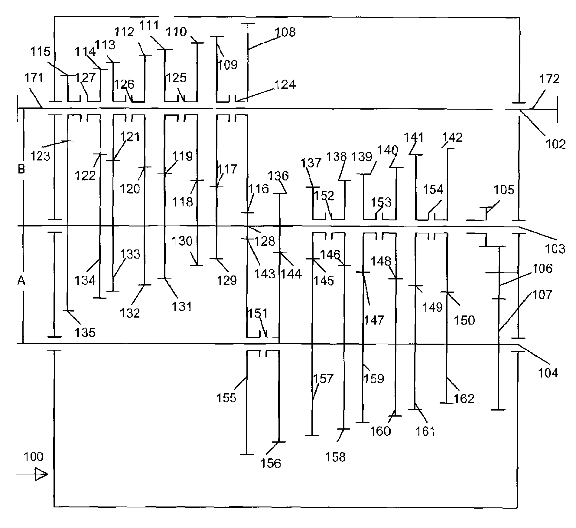
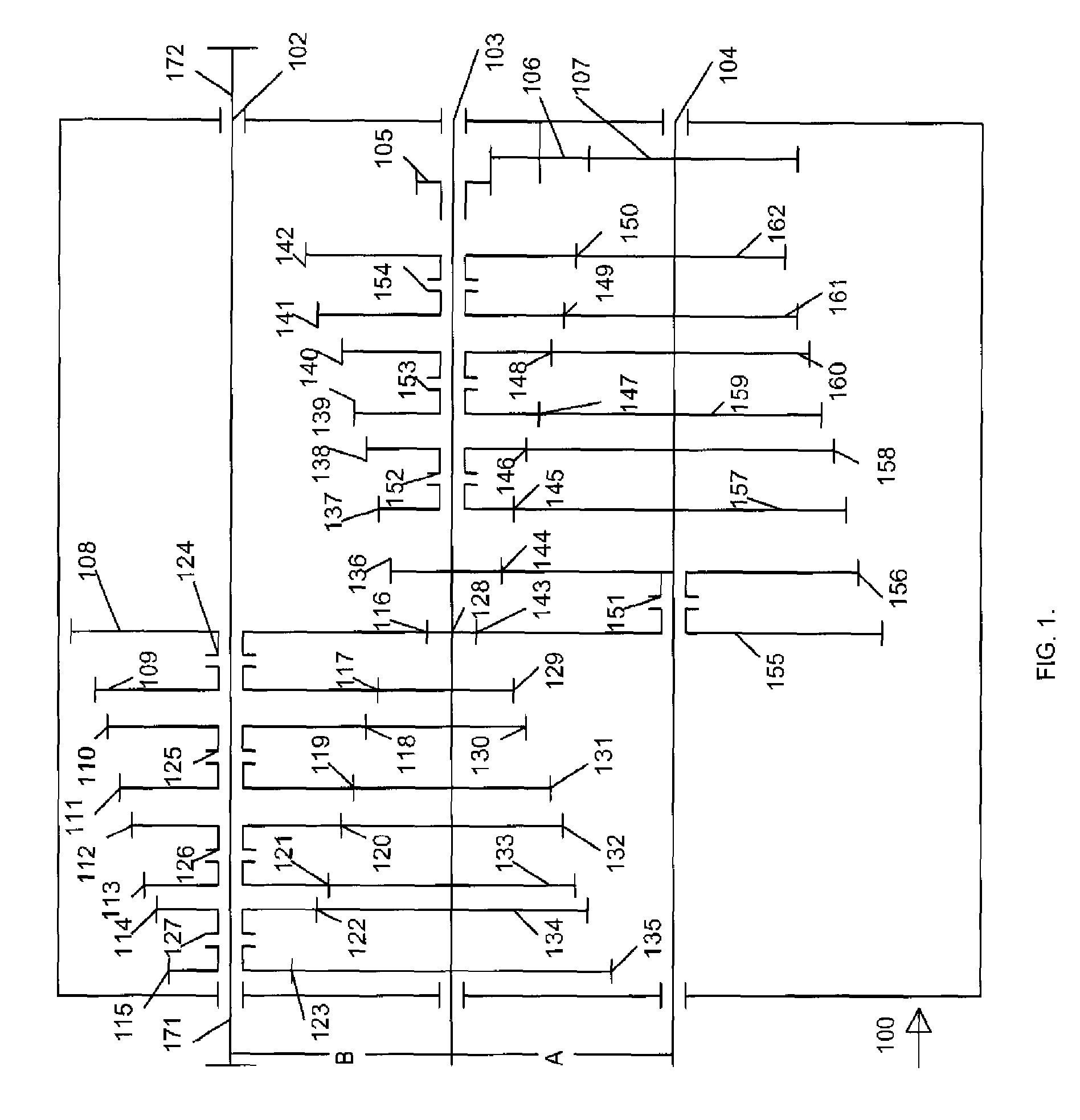
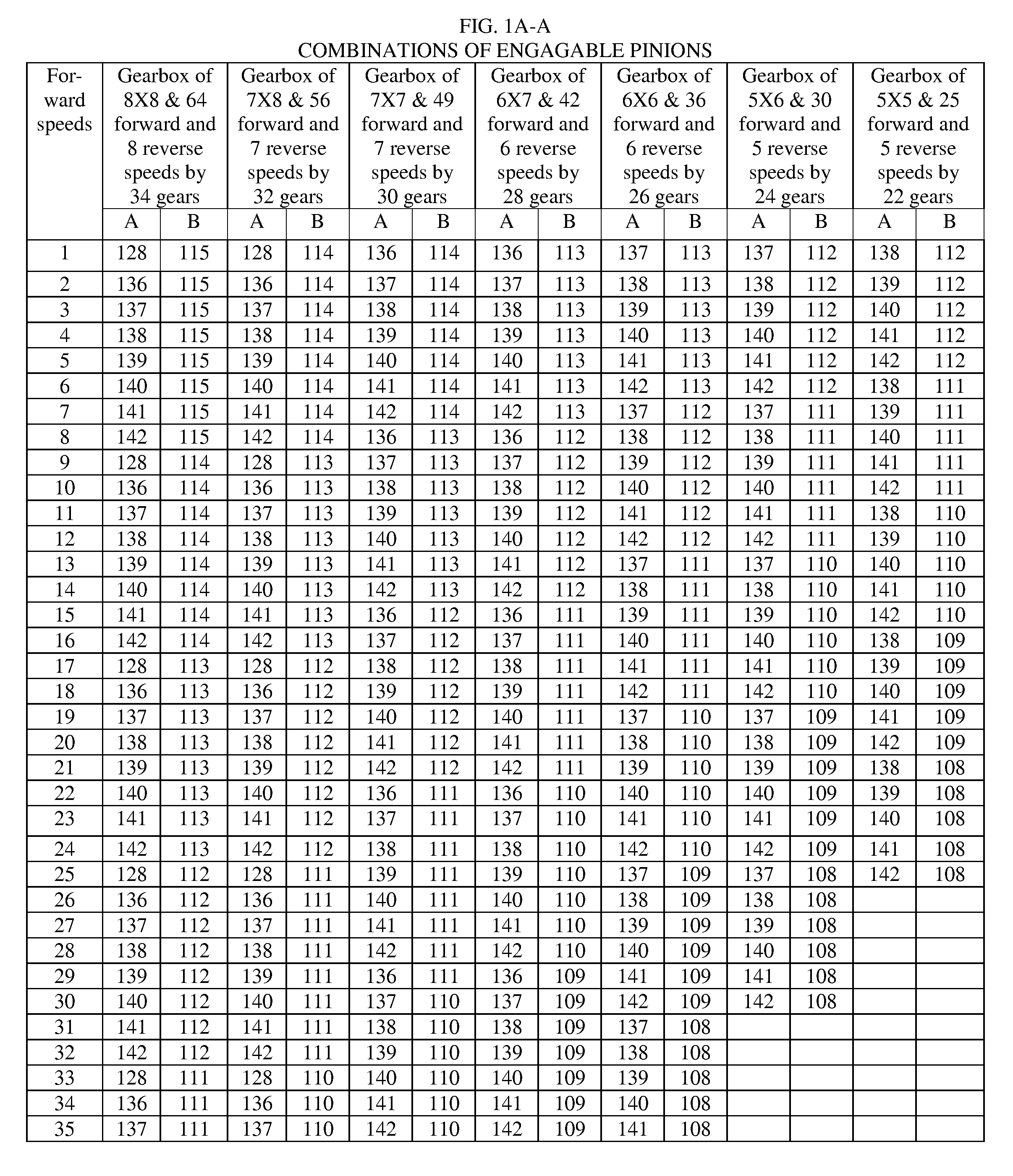
[0087]In two designs in the same frame, members 101 shown in FIGS. 1 and 1C there are 64 and 65 gears of forward included 24 overdrive speeds and 8 and 16 reverse speeds. One design of range type has a mathematical gearbox formula 8×8 shown in FIG. 1. Other design of range-splitter type is compound MDUFEE gearbox family has a mathematical gearbox formula 8×8+1 shown in FIG. 1C.

[0088]Other difference is intermediate shaft 103 is second output shaft 103 of 16 reverse speeds connected to rear wheels. This provide to eliminate reverse mechanism comprising gears 105, 106, and 107 and to add one gear for forward speeds but to produce direct speed in addition than design shown in FIG. 1, which has described below.

[0089]A MDUFEE gearbox family 100 has frame members 101 supporting drive shaft 102, intermediate shaft 103 and output shaft 104 supported units A and B.

[0090]Power enters to left side of the MDUFEE gearbox family 100 on outward end 171 of the drive shaft 102 or on opposed outward ...

second embodiment

[0102]In the second embodiment, shown in FIG. 2, there are 96 gears of forward included 47 overdrive speeds and 24 reverse speeds available from MDUFEE gearbox family 200 having mathematical gearbox formula 4×4×6 in order. There are three units.

[0103]MDUFEE gearbox family 200 has frame members 201 supporting drive shaft 202, first intermediate shaft 203, second intermediate shaft 204 and output shaft 205.

[0104]Power may enter the MDUFEE gearbox family 200 on the left side on outward end 271 of the drive shaft 202 or on opposite outward end 272 if the drive shaft 202 in MDU gearbox 200 is turned around for using the opposed side of teeth on the gears. A drive shaft 202 supported two double synchronizer clutches 217 and 218 with pinions 209, 210, 211 and 212, which may be separately selected.

[0105]When pinions 209, 210, 211 or 212 is selected, it engages drive shaft 202, and engages and turns gears 219, 220, 221, 222, respectively, on first intermediate shaft 203 to form gearsets 213,...

third embodiment

[0117]In the third embodiment shown in FIG. 3 there are 108 forward and 27 reverse speeds included 36 overdrive forward and 9 overdrive reverse speeds. MDUFEE gearbox family 300 of mathematical gearbox formula 3×3×3×4 has frame members 301 supporting drive shaft 302, first intermediate shaft 303, second intermediate shaft 304, second intermediate shaft 305 and output shaft 306.

[0118]Power may enter the MDUFEE gearbox family 300 on the left side on outward end 371 of the drive shaft 302 or on opposite outward end 372 if the drive shaft 302 is turned around for using the opposed side of teeth on the gears. Power entering at outward end 371 enters single synchronizer clutch 317 with pinion 312 and double synchronizer clutch 316 have pinions 310 and 311 which may be separately selected.

[0119]When pinion 310 or 311 or 312 is selected, it engages drive shaft 302, and engages and turns gear 318 or 319 or 320, respectively, on first intermediate shaft 303 to form gearset 313 or 314 or 315, ...


PUM


Abstract

A motorized machine with a “mutually definite units of energy for forced energy economy” (MDUFEE) gearbox family with a simplified shifting pattern of shifting mechanisms to cause a real gear dependence on mechanical inertia created by the weight of a load and a fast changeable resistant force in response to the movement. Each gearbox includes a sufficient number of gearsets with gear ratios selected from a faltering geometric sequence and arranged to provide a sufficient number of torques and overdrive speeds to the output shaft to satisfactorily operate the machine over a conventional range of machine speeds and at least limit the use of the acceleration system in the motor to reduce the heat and power generated from a the motor to less than 50 percent that used to generate a similar conventional range of machine speeds using a motor with a conventional gear box.

Description

CROSS REFERENCE TO RELATED APPLICATIONS[0001]This application claims the benefit of PPA App. No. 60 / 840,665 filed 2006 Aug. 28 by the Vladimir Abramov.FIELD OF THE INVENTION[0002]This invention relates to a gearbox with at least two independent shafts from other; each shaft supported two pair gearsets and more having degrees of constant ratios in a geometric sequence and / or faltering geometric sequence to provide both a number of torques and a number of overdrive speeds shifting by at least two levers in manual regime that is switched to semi-automatic and automatic regimes.BACKGROUND OF THE INVENTION[0003]There is a need for power systems to move land, sea and air transporting vehicles, heavy equipment, conveyer system, and machine tools to produce parts with dramatically increased fuel, natural gas and / or electricity efficiency. In addition, there is a need for improvement in the maneuverability of land, sea and air transporting vehicles. Also there is a need to extend the field o...

Claims


Application Information

Patent Timeline
Patent Type & Authority Patents(United States)
IPC IPC(8): F16H3/02
CPCF16H3/093F16H3/097F16H37/043Y10T74/19167F16H2200/0065Y10T74/19242F16H2200/0017
Inventor ABRAMOV, VLADIMIR
Owner ABRAMOV VLADIMIR
Why Eureka
Try Eureka