Method for distributed power harvesting using DC power sources

a technology of distributed dc power source and power source, which is applied in the integration of power network operation system, dc network circuit arrangement, and dc-ac conversion without reversal, etc., can solve the problems of large conduction loss, inability to operate at best achievable efficiency, and inability to optimize the power draw of each individual panel, so as to improve the reliability of components within the load and ensure safe operation voltage

Active Publication Date: 2011-09-06
SOLAREDGE TECH LTD
View PDF148 Cites 295 Cited by
  • Summary
  • Abstract
  • Description
  • Claims
  • Application Information

AI Technical Summary

Benefits of technology

[0042]According to aspects of the invention, a method for improving the reliability of components within the load in a distributed power system having a plurality of DC power sources coupled to a central load is provided, comprising: coupling the DC power sources to the central load; maintaining the input to the central load to a fixed predetermined voltage, the voltage being a safe operating voltage for the components within the load; varying the current input to the central load according to the power drawn from the DC power sources. The central load may comprise a DC / AC inverter, and the step of maintaining the input comprises maintaining the input voltage to the inverter. Coupling the DC power sources may comprise coupling each of a plurality of solar panels to a respective converter from a plurality of converters, and coupling all of the converters to the inverter. The method may further comprise operating each converter to boost the voltage obtained from a respective solar panel as soon as the respective solar panel starts to output electrical energy.

Problems solved by technology

Conversely, a serial connection may fail to provide the required current, so that several strings of serial connections may need to be connected in parallel to provide the required current.
For example, various inconsistencies in manufacturing may cause two identical sources to provide different output characteristics.
The problem facing the solar array designer is to produce a standard AC current at 120V or 220V root-mean-square (RMS) from a combination of the low voltages of the solar panels.
The delivery of high power from a low voltage requires very high currents, which cause large conduction losses on the order of the second power of the current (I2).
While this configuration is advantageous in terms of cost and architecture simplicity, several drawbacks have been identified in the literature for such architecture.
One recognized drawback is inefficiencies cause by non-optimal power draw from each individual panel, as explained below.
Consequently, the arrangement is not operated at best achievable efficiency.
Forcing a single current through all of the panels of the string causes the individual panels to work at a non-optimal power point and can also cause panels which are highly mismatched to generate “hot spots” due to the high current flowing through them.
Due to these and other drawbacks of conventional centralized methods, the solar panels have to be matched properly.
In conventional multiple string configurations all strings have to be composed of exactly the same number of solar panels and the panels are selected of the same model and must be install at exactly the same spatial orientation, being exposed to the same sunlight conditions at all times. This is difficult to achieve and can be very costly.
As noted in some of the above cited works, integrating inverters into the individual cells has many drawbacks, including high costs, low safety (especially in solar installations), and reliability.
However, incorporating MPPT into each panel is still problematic in serial application, as each MPPT would attempt to drive its source at different current, while in a serial connection the same current must flow through all of the panels.
Moreover, it is unclear what type of DC-DC converter would provide the best results and how to incorporate an MPPT into such an arrangement.
As already mentioned above, various environmental and operational conditions impact the power output of DC power sources.
Owners and even professional installers find it difficult to verify the correct operation of the solar system.
With time, many other factors, such as aging, dust and dirt collection and module degradation affect the performance of the solar array.
Since these cells are expensive, they are usually used in CPV applications which call for smaller cells.
However, the power output of CPV installations now depends upon fluctuations in the intensity of different parts of the spectrum of the sun (and not only the total intensity), and imperfections or distortions in the lenses or mirrors used.
Another field in which traditional photovoltaic installations face many problems is the developing market of building-integrated photovoltaics (BIPV).
Thus, BIPV installations suffer greatly from local partial shading due to the existence of other structural elements in the vicinity of the panels.
Since in traditional solutions the panels are stringed together to a joint MPPT, much power is lost.
Yet another problem with traditional installations is the poor energy utilization in cases of low sun-light.
If there is low light, the aggregated voltage from the panels may not reach this minimal value, and the power is thus lost.
In practice, however, individual panels and strings are generally either not tested at all or tested only prior to connection.
This happens because current measurement is done by either a series connection to the solar array or a series resistor in the array which is typically not convenient.
Therefore, the performance information provided by monitoring at the inverter 104 is usually not sufficient to understand if power loss is due to environmental conditions, from malfunctions or from poor installation or maintenance of the solar array.
Furthermore, integrated information does not pinpoint which of solar panels 101 is responsible for a detected power loss.

Method used


Image

  • Method for distributed power harvesting using DC power sources
  • Method for distributed power harvesting using DC power sources
  • Method for distributed power harvesting using DC power sources

Examples


Embodiment Construction

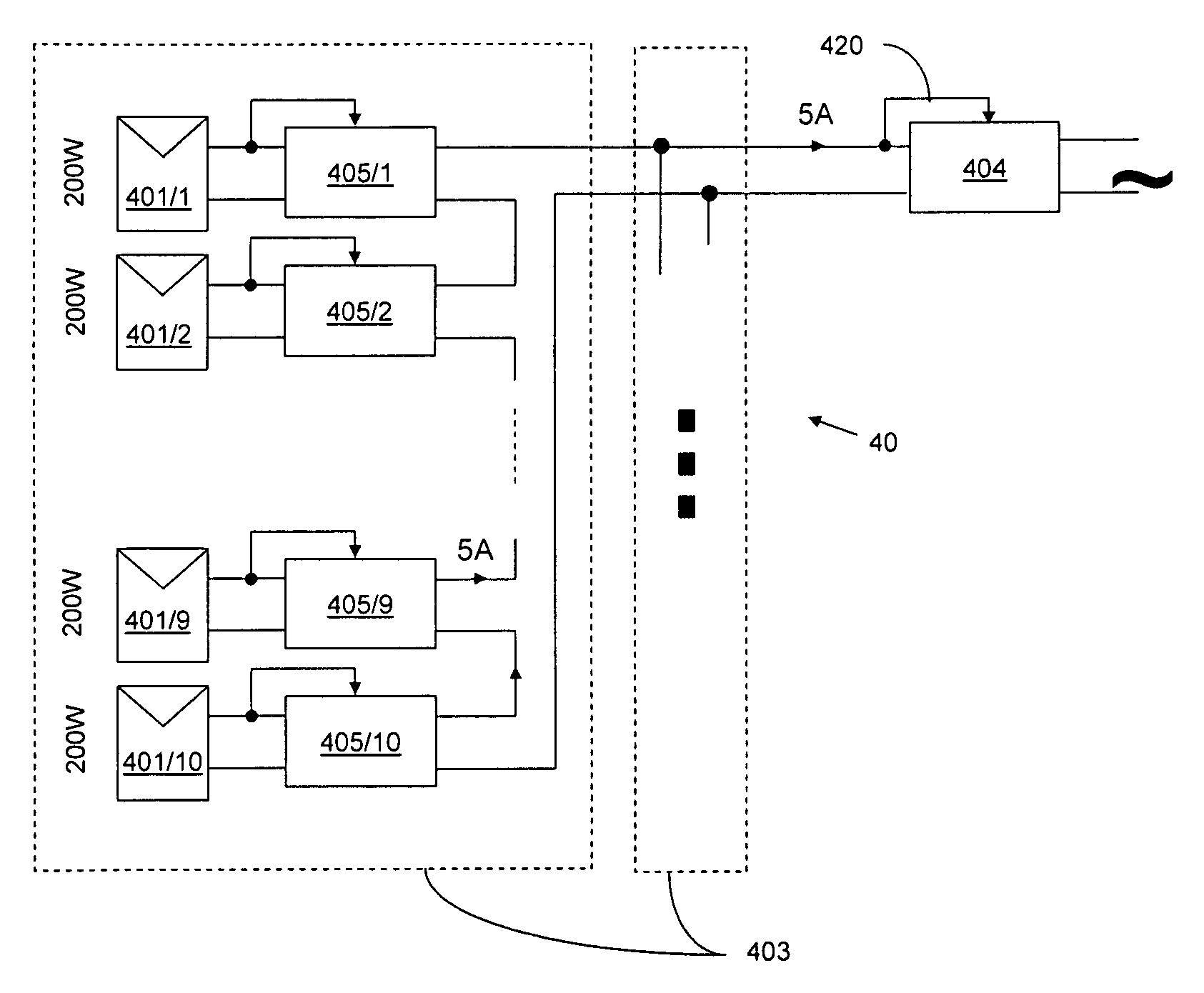
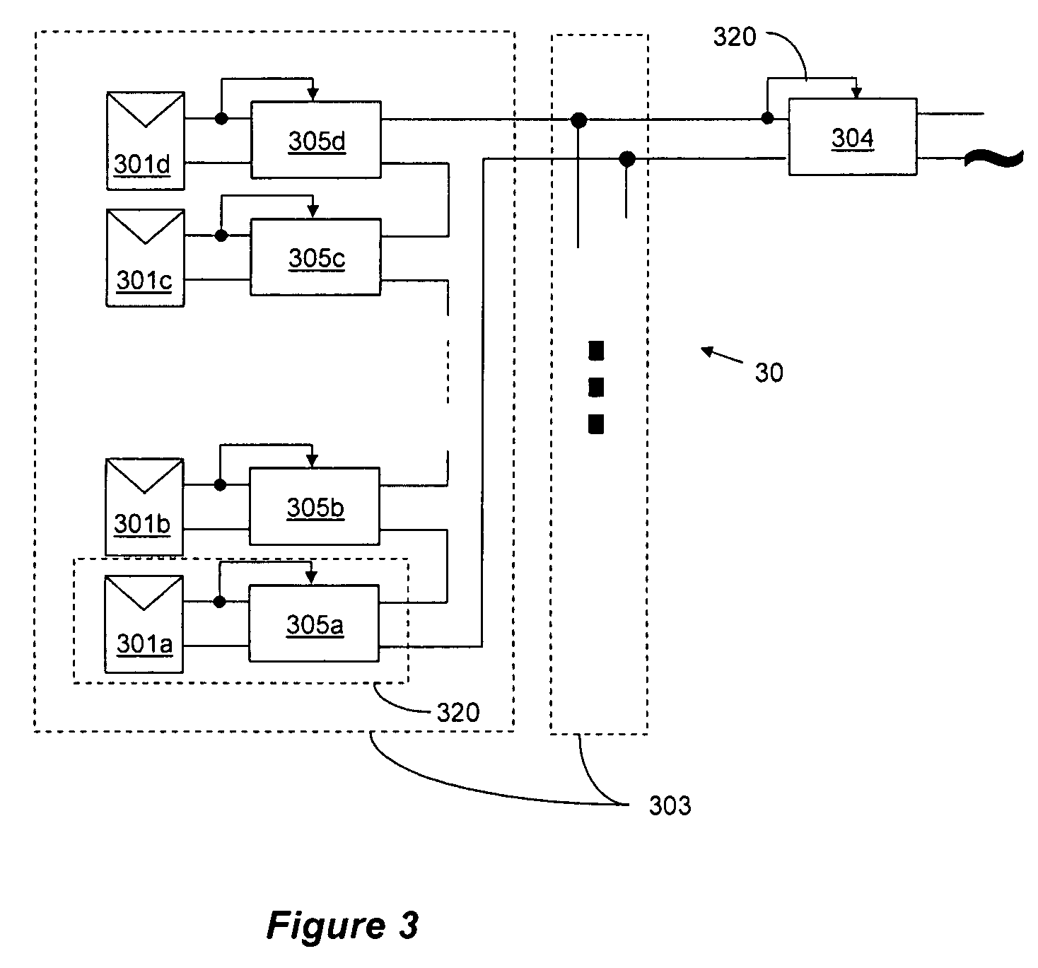
[0056]The topology provided by the subject invention solves many of the problems associated with, and has many advantages over, the prior art topologies. For example, the inventive topology enables serially connecting mismatched power sources, such as mismatched solar panels, panel of different models and power ratings, and even panels from different manufacturers and semiconductor materials. It allows serial connection of sources operating under different conditions, such as, e.g., solar panels exposed to different light or temperature conditions. It also enables installations of serially connected panels at different orientations or different sections of the roof or structure. This and other features and advantages will become apparent from the following detailed description.

[0057]Aspects of the present invention provide a system and method for combining power from multiple DC power sources into a single power supply. According to aspects of the present invention, each DC power so...


PUM


Abstract

A system and method for combining power from DC power sources. Each power source is coupled to a converter. Each converter converts input power to output power by monitoring and maintaining the input power at a maximum power point. Substantially all input power is converted to the output power, and the controlling is performed by allowing output voltage of the converter to vary. The converters are coupled in series. An inverter is connected in parallel with the series connection of the converters and inverts a DC input to the inverter from the converters into an AC output. The inverter maintains the voltage at the inverter input at a desirable voltage by varying the amount of the series current drawn from the converters. The series current and the output power of the converters, determine the output voltage at each converter.

Description

CROSS-REFERENCE TO RELATED APPLICATIONS[0001]This Application claims priority to U.S. Provisional Patent Applications, Ser. No. 60 / 868,851, filed Dec. 6, 2006, and titled “Distributed Solar Array Monitoring, Management and Maintenance,” Ser. No. 60 / 868,893, filed Dec. 6, 2006, and titled “Distributed Power Harvesting System for Distributed Power Sources,” 60 / 868,962, filed Dec. 7, 2006, and titled “System, Method and Apparatus for Chemically Independent Battery,” Ser. No. 60 / 908,095, filed Mar. 26, 2007, and titled “System and Method for Power Harvesting from Distributed Power Sources,” and Ser. No. 60 / 916,815, filed May 9, 2007, and titled “Harvesting Power From Direct Current Power Sources,” the entire content of which is incorporated herein by reference. Further, this Application is related to ordinary U.S. Patent Applications titled “Monitoring of Distributed Power Harvesting Systems Using DC Power Sources”, Ser. No. 11 / 951,419 and “Battery Power Delivery Module”, Ser. No. 11 / 95...

Claims


Application Information

Patent Timeline
Patent Type & Authority Patents(United States)
IPC IPC(8): H02J1/00H02J3/00
CPCH02J3/385H02J3/18H02M3/1582H02M2001/007H02M2001/0077H02J3/387Y02E10/58H02J2300/30H02J2300/26H02J3/381Y02E10/56Y04S20/222Y02B70/3225H02M1/0077H02M1/007H02J3/38H02M7/44
Inventor ADEST, MEIRHANDELSMAN, LIORGALIN, YOAVFISHELOV, AMIRSELLA, GUY
Owner SOLAREDGE TECH LTD
Why Eureka
Try Eureka