Synchronous phase detection circuit

a phase detection circuit and synchronous technology, applied in the field of phase detection circuits, can solve the problems of inability to provide an output signal, small filter output, noise, etc., and achieve the effect of accurate measurement of phase differen

Active Publication Date: 2011-09-06
STICHTING VOOR DE TECH WETENSCHAPPEN
View PDF10 Cites 5 Cited by
  • Summary
  • Abstract
  • Description
  • Claims
  • Application Information

AI Technical Summary

Benefits of technology

[0010]It is an object of the present invention to provide a circuit which overcomes the disadvantages from the prior art and generates a signal which is a more accurate measure of the phase difference between an input signal obscured by noise and a reference signal.
[0011]It is an additional object of the present invention to determine the temperature of a substrate by accurately measuring the phase-shift of an electrothermal filter embedded in the same substrate.

Problems solved by technology

As a result, the filter's output will be small and will be obscured by noise.
The phase detection circuit of the prior art does not provide an output signal that is an accurate measure of the phase difference between the input and reference signals.
Although the control voltage applied to the voltage-controlled phase shifter is related to this phase difference, their relationship is ill-defined, since the phase-shifter is a complex analog system that is sensitive to the tolerances and linearity of its constituent parts.
Another drawback of phase detection circuit of the prior art is that it is sensitive to any offset present at the output of the chopper.
This offset may be caused by the asymmetric switching spikes produced by a practical chopper.
A further source of error arises if the duty-cycle of the signal applied to the control input of the chopper is not exactly 50%.
Any such DC level will then lead to a change in the average level at the output of the chopper, and so to an error in the detected phase difference.

Method used


Image

  • Synchronous phase detection circuit
  • Synchronous phase detection circuit
  • Synchronous phase detection circuit

Examples


first embodiment

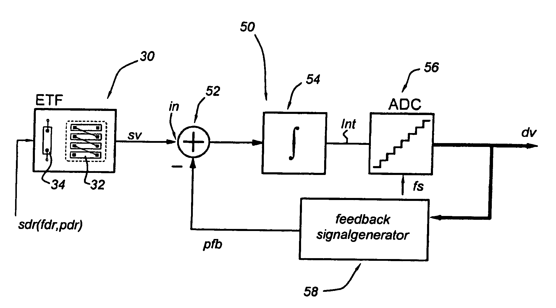
[0058]FIG. 1 shows schematically a synchronous phase detection circuit in accordance with the present invention.

[0059]In the present invention the synchronous phase detection circuit (synchronous phase detector) is based on the idea that the source circuit is driven at a constant frequency.

[0060]In this embodiment, the synchronous phase detection circuit 50 according to the present invention comprises a phase difference circuit 52, an integrator circuit 54, a digitizing circuit 56 and a feedback signal generator 58.

[0061]An input node of the source circuit 30 is coupled to a driver (not shown) which provides a driving signal sdr as a reference signal with driving frequency fdr and a reference phase pdr.

[0062]The source circuit 30 is arranged for producing a response signal responsive to the driving signal sdr, which is represented by a periodic signal sv with frequency f0 and phase p0. Typically, the frequency f0 of the periodic signal sv is equal to the driving frequency fdr.

[0063]...

second embodiment

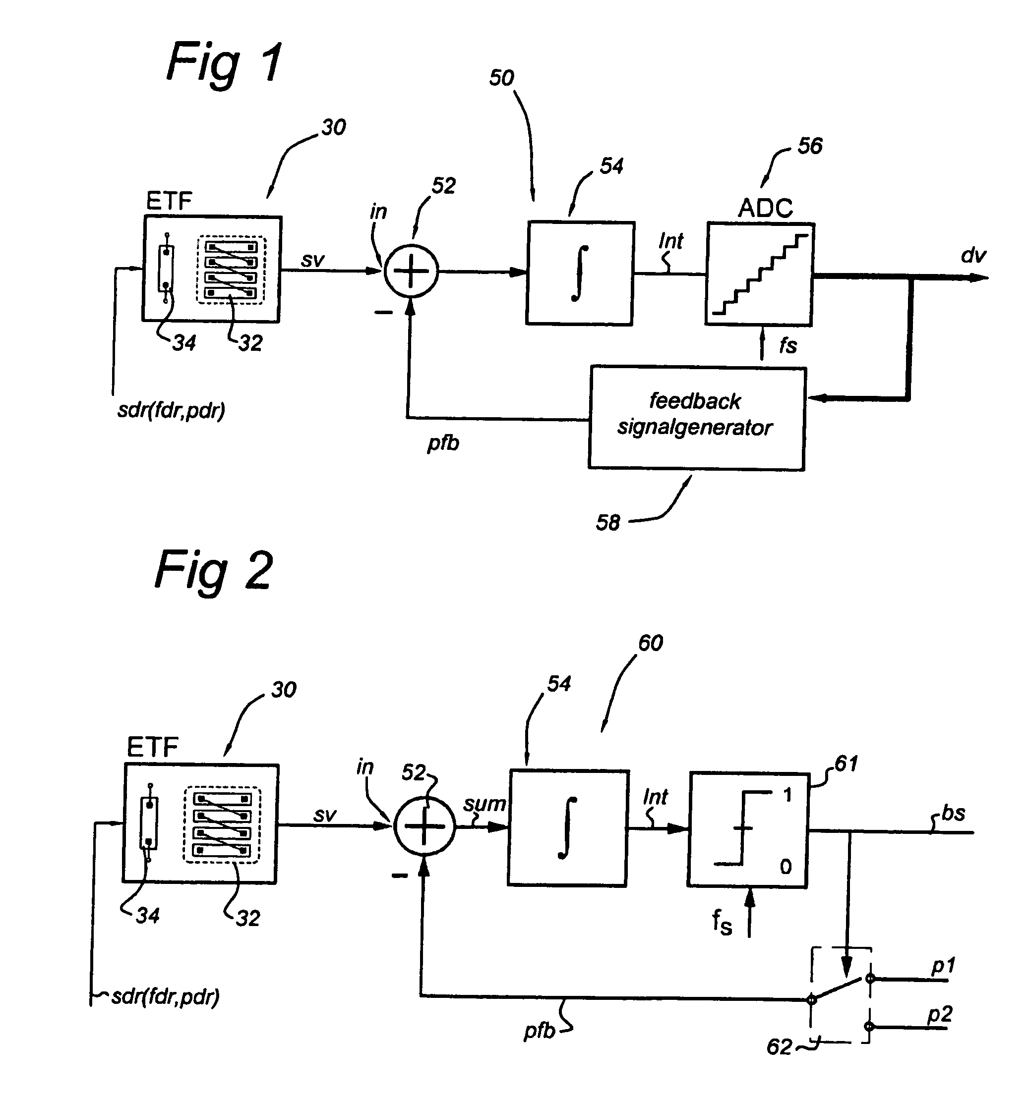
[0080]FIG. 2 shows schematically the synchronous phase detection circuit in accordance with the present invention.

[0081]In FIG. 2, entities with the same reference number as shown in the preceding figures refer to the corresponding entities in the preceding figures. In the second embodiment, the synchronous phase detection circuit 60 according to the present invention comprises a phase difference circuit 52, an integrator circuit 54, a 1-bit analog-digital converter 61 and a binary (two-level) phase generator 62.

[0082]The second embodiment 60 differs from the first embodiment in that the n-level analog-digital converter 56 is replaced by a 1-bit analog-digital converter or comparator 61, and the n-level discrete phase generator 58 is replaced by the binary phase generator 62. The other entities are identical or equivalent to the corresponding entities in the preceding figures and will not described here in detail.

[0083]The error signal sum is substantially zero when the feedback pha...

third embodiment

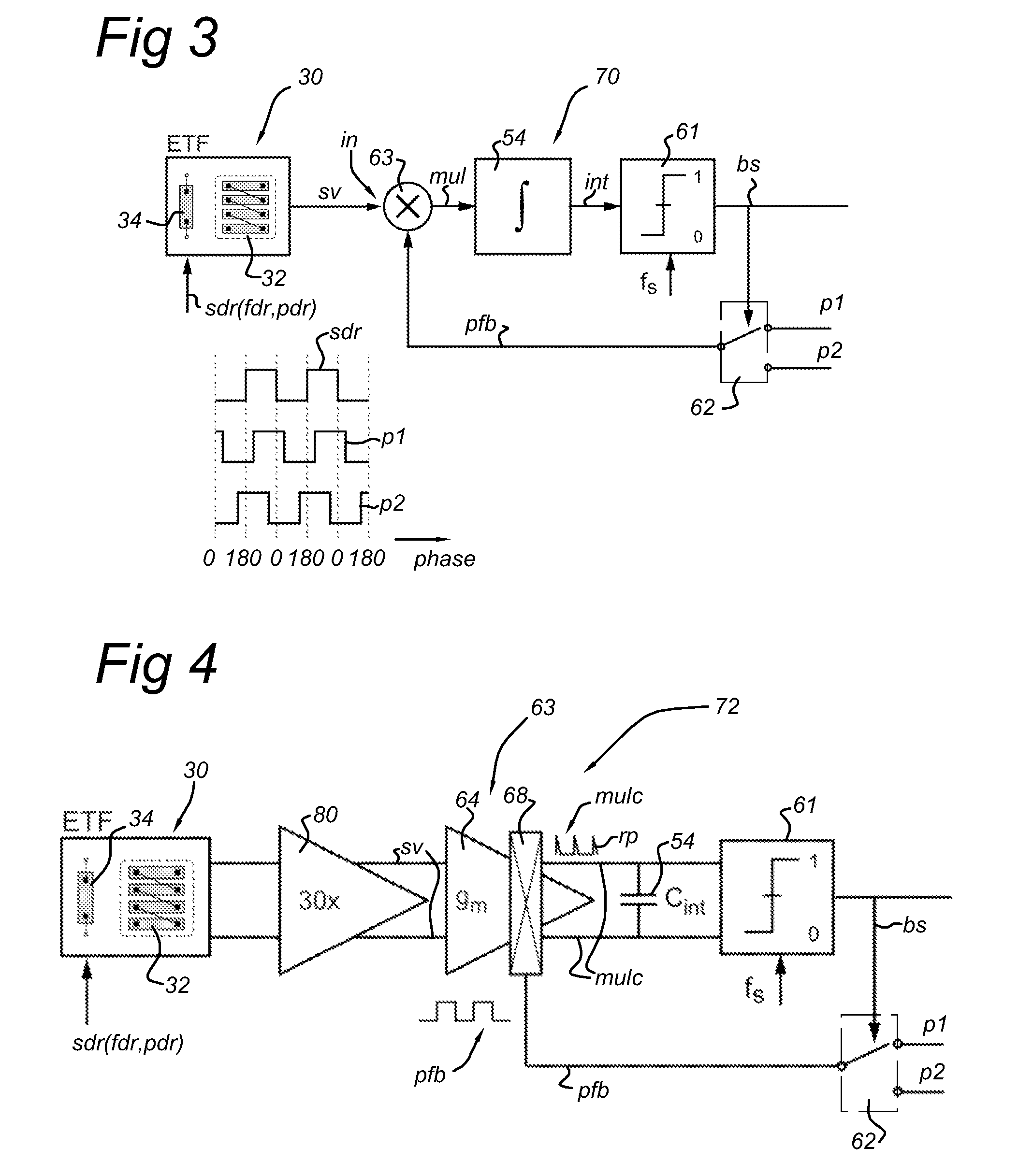
[0092]FIG. 3 shows schematically the synchronous phase detection circuit in accordance with the present invention.

[0093]In FIG. 3 entities with the same reference number as shown in the preceding figures refer to the corresponding entities in the preceding figures. In the third embodiment, the synchronous phase detection circuit 70 according to the present invention comprises a multiplication circuit 63, an integrator circuit 54, a 1-bit analog-digital converter 61 and a binary phase generator 62.

[0094]The third embodiment 70 differs from the second embodiment in that the phase difference circuit is replaced by a multiplication circuit. The other entities are identical or equivalent to the corresponding entities in the preceding figures and will not described here in detail.

[0095]An output node of the source circuit 30 is coupled to a first input node of the multiplication circuit 63 for providing the periodic signal sv with frequency f0 and phase p0 to the multiplication circuit 63...


PUM


Abstract

A phase detection circuit determines phase difference between a periodic signal and a reference signal of substantially equal frequency. The circuit includes: a source input receiving the periodic signal; a feedback signal generator providing a feedback signal (PFB) with substantially the same frequency as the reference signal; a phase difference circuit coupled to the source input node and a second signal input node coupled to the feedback signal generator, determining an error signal from phase difference between the periodic signal and PFB; an integrator circuit integrating the error signal into an integration signal; and a digitizing circuit digitizing the integration signal. The feedback signal generator is coupled to the digitizing circuit, providing PFB based on the digitized integration signal, and selecting the phase of PFB from a number of fixed phases. The phase detection circuit generates a time-average of the phase of PFB selected from the plurality of fixed phases.

Description

FIELD OF THE INVENTION[0001]This invention relates to a phase detection circuit for the measurement of phase differences between an input signal obscured by noise and a reference signal. Also the invention relates to a method for method for determining a phase difference between a periodic signal and a reference signal.BACKGROUND OF THE INVENTION[0002]When driven by a signal at a substantially constant reference frequency, the output signal of an electrothermal filter will experience a certain phase-shift.[0003]WO / 2006 / 132531 describes an oscillator based on thermal diffusion, which comprises a frequency locked loop which is coupled to an electrothermal filter and allows measurement of the absolute temperature T of the electrothermal filter. The frequency of the oscillator is inversely proportional to 1 / T1.8. Using this oscillator it is observed that the phase shift between the driving signal of the electrothermal filter and the phase of the periodic signal at the output of the filt...

Claims


Application Information

Patent Timeline
Patent Type & Authority Patents(United States)
IPC IPC(8): G01R25/00H03D13/00
CPCH03L7/0814H03L7/085H03M3/456H03M3/43H03M3/464H03L7/091G01R25/04
Inventor MAKINWA, KOFI AFOLABI ANTHONYVAN VROONHOVEN, CASPAR PETRUS LAURENTIUS
Owner STICHTING VOOR DE TECH WETENSCHAPPEN
Why Eureka
Try Eureka