Imaging lens

a technology of imaging lens and optical glass, which is applied in the field of imaging lens, can solve the problems of increasing manufacturing cost, complicated manufacturing steps, and inability to maintain optical performance, and achieves the effects of high softening temperature, high softening temperature optical glass material, and high softening temperature optical

Inactive Publication Date: 2011-09-06
SEIKOH GIKEN
View PDF24 Cites 13 Cited by
  • Summary
  • Abstract
  • Description
  • Claims
  • Application Information

AI Technical Summary

Benefits of technology

[0062]According to the first and second imaging lenses of the present invention, in the first junction type compound lens constituting the imaging lenses, the first and the third lenses, which are formed of a curable resin material, sandwich and are indirectly bonded to the second lens, which is formed of a high softening temperature optical glass material. In the second junction type compound lens, the fourth and the sixth lenses, which are formed of a curable resin material, sandwich and are indirectly bonded to the fifth lens, which is formed of a high softening temperature optical glass material. And in the third junction type compound lens, the seventh and the ninth lenses, which are formed of a curable resin material, sandwich and are indirectly bonded to the eighth lens, which is formed of a high softening temperature optical glass material.
[0063]In the first imaging lens of the present invention, the first junction type compound lens may be comprised of the first lens, the second lens and the third lens arranged in this sequence from the object side to the image side, where the first lens, the second lens and the third lens are formed of a curable resin material. The second junction type compound lens may be comprised of the fourth lens, the fifth lens and the sixth lens arranged in this sequence from the object side to the image side, where the fourth lens, the fifth lens and the sixth lens are formed of a curable resin material. And the third junction type compound lens may be comprised of the seventh lens, the eighth lens and the ninth lens arranged in this sequence from the object side to the image side, where the seventh lens, the eighth lens and the ninth lens are formed of a curable resin material. In this case, the first lens and the second lens are directly bonded or indirectly bonded, and the second lens and the third lens are directly bonded or indirectly bonded. The fourth lens and the fifth lens are directly bonded or indirectly bonded, and the fifth lens and the sixth lens are directly bonded or indirectly bonded. The seventh lens and the eighth lens are directly bonded or indirectly bonded, and the eighth lens and the ninth lens are directly bonded or indirectly bonded.
[0064]The high softening temperature optical glass material here refers to an optical glass material of which softening temperature is higher than both the temperature of reflow processing and the maximum environmental temperature in the design specifications of the junction type compound lens. In the following description, the phrase “high softening temperature optical glass material” is used when a thermal characteristic of the optical glass material is discussed, and the simple phrase “optical glass material” may be used when an optical characteristic is discussed.
[0065]The curable resin material does not soften once curing processing is performed, even if the temperature rises more than a predetermined temperature. This nature of the curable resin material is different from the nature of a plastic resin material, such as plastic material, which becomes soft and plasticized if the material is exposed to a temperature that exceeds a predetermined temperature, which is referred to as a “softening temperature” (also referred to as a “glass transition temperature”). In other words, once curing processing is performed and material solidifies, the geometric shape of the curable resin material does not change.
[0066]Therefore the geometric shapes of the first lens, the third lens, the fourth lens, the sixth lens, the seventh lens and the ninth lens do not change, and optical performance thereof does not deteriorate even if the lenses are placed in a high temperature environment. The second lens, the fifth lens and the eighth lens are also formed of a high softening temperature optical glass material, so the optical performance thereof does not deteriorate even under a high temperature environment. In the case of the second lens, the fifth lens and the eighth lens formed of a curable resin material as well, the optical performance thereof does not deteriorate even under a high temperature environment. The high temperature environment here refers to a temperature environment higher than both the temperature in reflow processing and the maximum temperature in the design specifications of the junction type compound lens.
[0067]Therefore the optical performance of the first junction type compound lens, the second junction type compound lens and the third junction type compound lens is guaranteed even in a high temperature environment, where the temperature is at the maximum, that is assumed in reflow processing and when the imaging lens is in use.

Problems solved by technology

Therefore a heat resistant socket component is used for installing an imaging lens in order to prevent thermal deformation of the imaging lens in a high temperature environment, which makes it impossible to maintain optical performance thereof.
However, using a heat resistant socket component for installing an imaging lens makes the manufacturing steps complicated, and increases the manufacturing cost, including the cost of this heat resistant socket.
A conventional imaging lens made of plastic material cannot meet this demand.
Since the temperature at which the high softening temperature mold glass material softens is several hundred degrees or more, the deterioration of optical performance of an imaging lens in a high temperature environment can be avoided, but at the moment, an imaging lens made of mold glass material is not very popular, because the manufacturing cost is very high.

Method used


Image

  • Imaging lens
  • Imaging lens
  • Imaging lens

Examples


embodiment 1

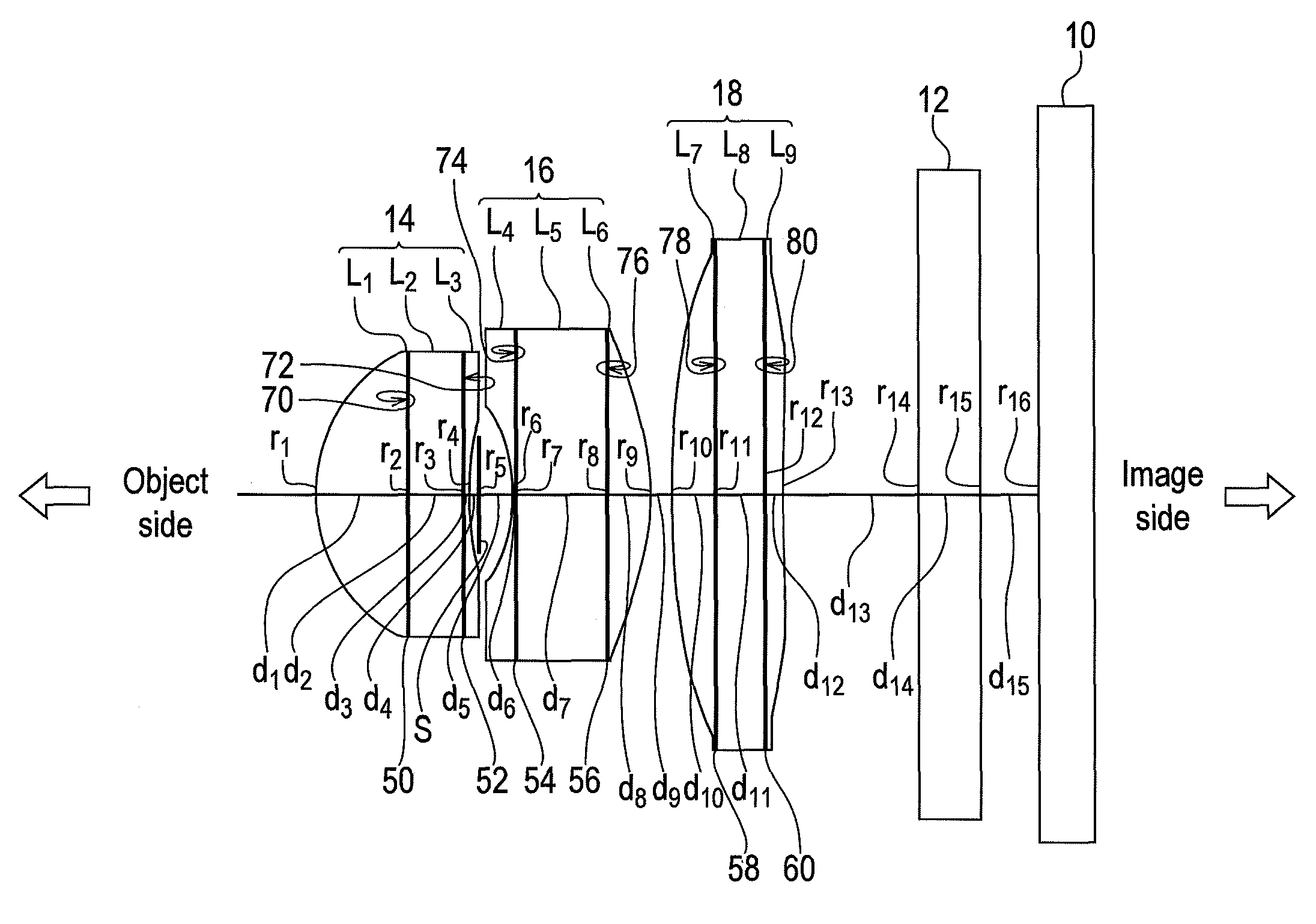
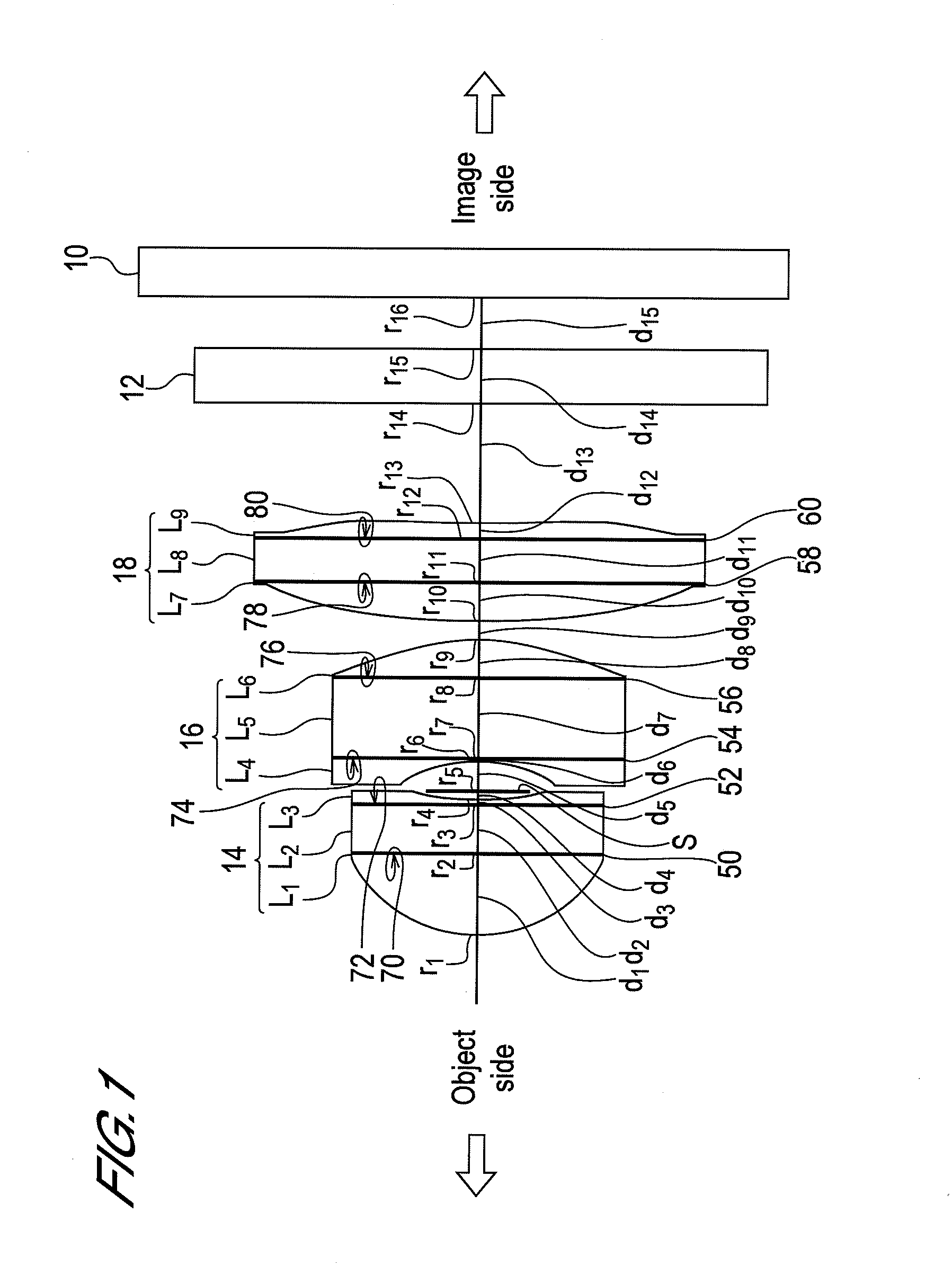
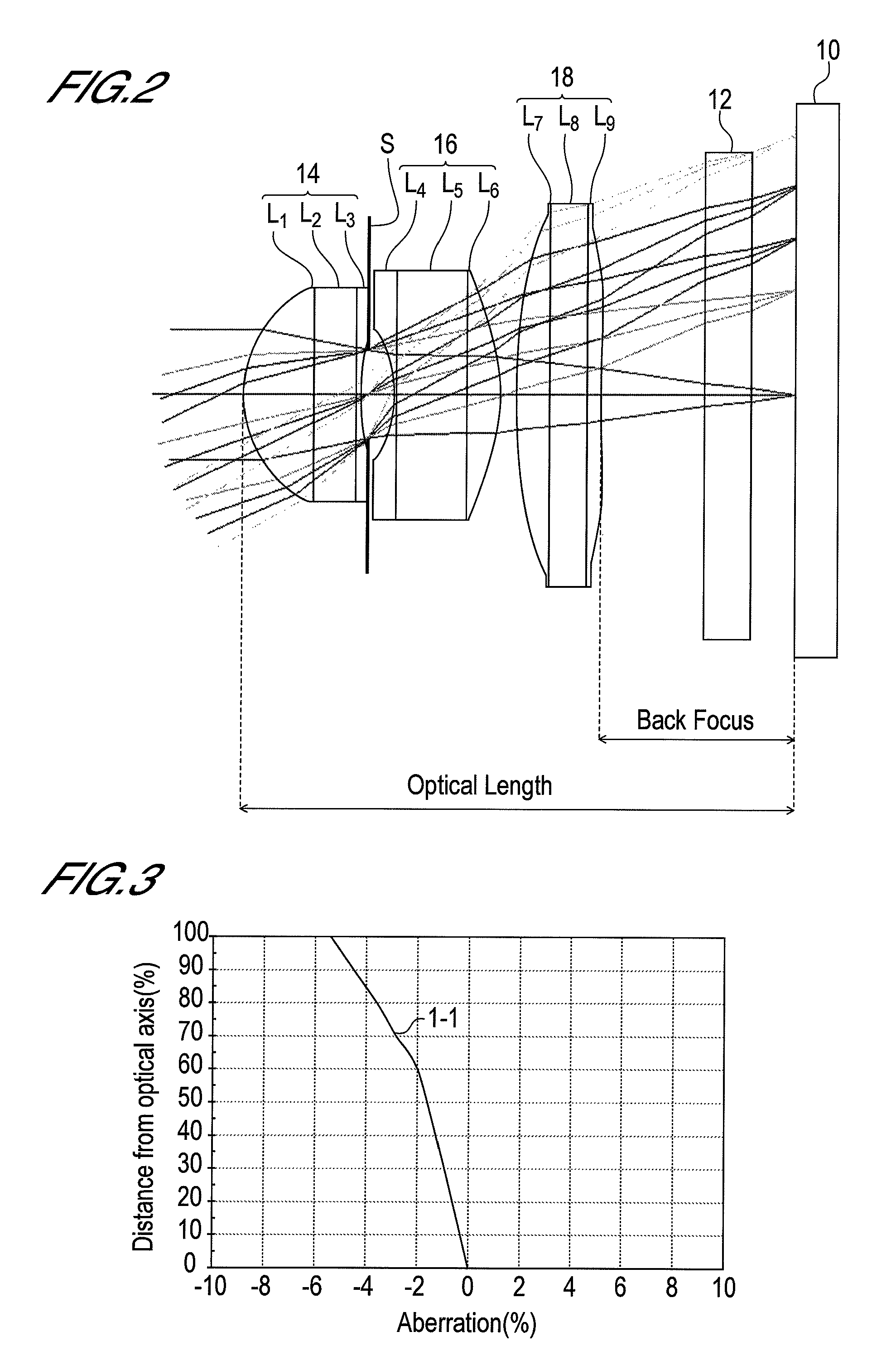
[0187]Embodiment 1 is an embodiment of the first imaging lens of the present invention, where the first lens L1, the third lens L3, the fourth lens L4, the sixth lens L6, the seventh lens L7 and the ninth lens L9 are formed of transparent curable silicone resin SMX-7852 (made by Fuji Polymer Industries Co. Ltd.), and the second lens L2, the fifth lens L5 and the eighth lens L8 are formed of optical glass BK7 (made by Ohara Inc.).[0188](A) The refractive index N1 of the first lens L1 is N1=1.51000.[0189](B) The refractive index N2 of the second lens L2 is N2=1.51633.[0190](C) The refractive index N3 of the third lens L3 is N3=1.51000.[0191](D) The Abbe number ν1 of the first lens L1 is ν1=56.0.[0192](E) The Abbe number ν2 of the second lens L2 is ν2=64.0.[0193](F) The Abbe number ν3 of the third lens L3 is ν3=56.0.[0194](G) The refractive index N4 of the fourth lens L4 is N4=1.51000.[0195](H) The refractive index N5 of the fifth lens L5 is N5=1.51633.[0196](I) The refractive index N6...

embodiment 2

[0219]Embodiment 2 is an embodiment of the second imaging lens of the present invention, where the first lens L1, the third lens L3, the fourth lens L4, the sixth lens L6, the seventh lens L7 and the ninth lens L9 are formed of a transparent curable silicone resin SMX-7852 (made by Fuji Polymer Industries Co. Ltd.), and the second lens L2, the fifth lens L5 and the eighth lens L8 are formed of optical glass BK7 (made by Ohara Inc.)

[0220]The respective composing materials of the first to the ninth lens are the same as the above mentioned Embodiment 1, therefore |N2−N1|=|N2−N3|=|N5−N4|=|N5−N6|=|N8−N7|=|N8−N9|=0.00633, which satisfies the following Conditions (1), (2), (5), (6), (9) and (10). Also |ν2−ν1|=|ν2−ν3|=|ν5−ν4|=|ν5−ν6|=|ν8−ν7|=|ν8−ν9|=8.0, which satisfies the following Conditions (3), (4), (7), (8), (11) and (12).

[0221]FIG. 7 is a cross-sectional view of the imaging lens of Embodiment 2. As FIG. 7 shows, the first stop S1, to play a role of an aperture stop, is formed at a po...

embodiment 3

[0232]Embodiment 3 is an embodiment of the second imaging lens of the present invention, wherein the first lens L1, the third lens L3, the seventh lens L7, and the ninth lens L9 are formed of transparent curable silicone resin SR-7010 (made by Dow Corning Toray Co., Ltd.), the second lens L2 and the eighth lens L8 are formed of optical glass BK7 (made by Ohara Inc.), and the fifth lens L5 is formed of optical glass E-F5 (made by Hoya Corp). And the fourth lens L4 and the sixth lens L6 are formed of transparent curable silicone resin SMX-7877 (made by Fuji Polymer Industries Co. Ltd)).[0233](A) The refractive index N1 of the first lens L1 is N1=1.53000.[0234](B) The refractive index N2 of the second lens L2 is N2=1.51633.[0235](C) The refractive index N3 of the third lens L3 is N3=1.53000.[0236](D) The Abbe number ν1 of the first lens L1 is ν1=35.0.[0237](E) The Abbe number ν2 of the second lens L2 is ν2=64.0.[0238](F) The Abbe number ν3 of the third lens L3 is ν3=35.0.[0239](G) The ...


PUM


Abstract

The present invention is an imaging lens of which optical performance does not deteriorate even in a high temperature environment, various aberrations are well corrected, optical length is short, and back focus is sufficiently secured, the imaging lens comprising a first junction type compound lens, an aperture stop S, a second junction type compound lens, and a third junction type compound lens, which are arranged in this sequence from an object side to an image side. The first junction type compound lens comprises a first lens L1, a second lens L2 and a third lens L3 arranged in this sequence from the object side to the image side, the second junction type compound lens comprises a fourth lens L4, a fifth lens L5 and a sixth lens L6 arranged in this sequence from the object side to the image side, and the third junction type compound lens comprises a seventh lens L7, an eighth lens L8 and a ninth lens L9 arranged in this sequence from the object side to the image side. The first lens, the third lens, the fourth lens, the sixth lens, the seventh lens and the ninth lens are formed of a curable resin material, and the second lens, the fifth lens and the eighth lens are formed of a high softening temperature optical glass material.

Description

TECHNICAL FIELD[0001]The present invention relates to an imaging lens, and more particularly to an imaging lens that can be suitably mounted on a portable telephone or the like.BACKGROUND ART[0002]In a portable telephone with a built-in digital camera, an imaging lens is mounted on a printed circuit board. As a method for mounting an imaging lens on a printed circuit board, a reflow soldering processing is used. Hereafter the reflow soldering may simply be called “reflow”. Reflow processing is a method for soldering an electronic component on a printed circuit board, by placing a solder ball in advance at a location where an electronic component is connected, placing the electronic component there, heating to melt the solder ball, then cooling the solder down.[0003]Generally in mass production steps, a reflow step for performing reflow processing is used as a method for mounting electronic elements or such components as an imaging lens on a printed circuit board. If the reflow step ...

Claims


Application Information

Patent Timeline
Patent Type & Authority Patents(United States)
IPC IPC(8): G02B9/12G02B3/02
CPCG02B7/028G02B13/0035G02B13/006G02B13/00G02B13/18
Inventor DO
Owner SEIKOH GIKEN
Why Eureka
Try Eureka