
Glass manufacturing apparatus and a structural member thereof

a technology of glass manufacturing apparatus and hollow tube, which is applied in the direction of glass tempering apparatus, glass pressing apparatus, glass reforming apparatus, etc., can solve the problems of difficult glass production, conduction heating to hollow tube b, and electrode damage b>

Inactive Publication Date: 2011-09-13
ASAHI GLASS CO LTD
View PDF8 Cites 6 Cited by
  • Summary
  • Abstract
  • Description
  • Claims
  • Application Information

AI Technical Summary

Benefits of technology

The present invention provides a hollow tubular body for a conduit in a glass manufacturing apparatus, which prevents local-overheating in the electrode for conduction heating. The hollow tubular body has a ring electrode joined to the outer circumference of the hollow tube, at least one lead-out electrode joined to the outer edge of the ring electrode, and the ring electrode has a core portion of electrode made of platinum or platinum alloy and a thick portion made of a metallic material other than platinum or platinum alloy. The hollow tubular body can be heated by conduction heating and is suitable for manufacturing glass. The technical effects of the invention include preventing overheating, improving energy efficiency, and facilitating the production of high-quality glass.

Problems solved by technology

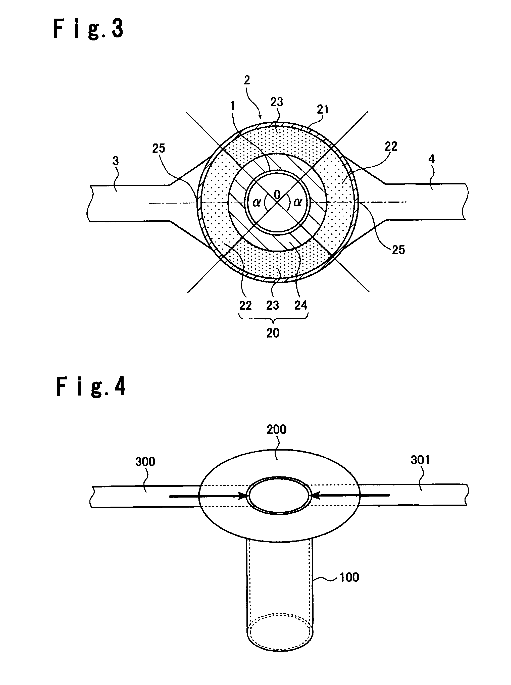
The occurrence of such local-overheating may destroy the electrode 200 due to a thermal stress.
If the electrode 200 is destroyed, conduction heating to hollow tube 100 becomes impossible whereby there causes a temperature difference between the molten glass and the hollow tube and it is difficult to produce glass.
When the current converges at the specified portion of the hollow tube 100, that portion is subject to local-overheating whereby the hollow tube may be damaged due to a thermal stress or the quality of molten glass passing through the hollow tube 100 may change.

Method used


Image

  • Glass manufacturing apparatus and a structural member thereof
  • Glass manufacturing apparatus and a structural member thereof
  • Glass manufacturing apparatus and a structural member thereof

Examples


example 1

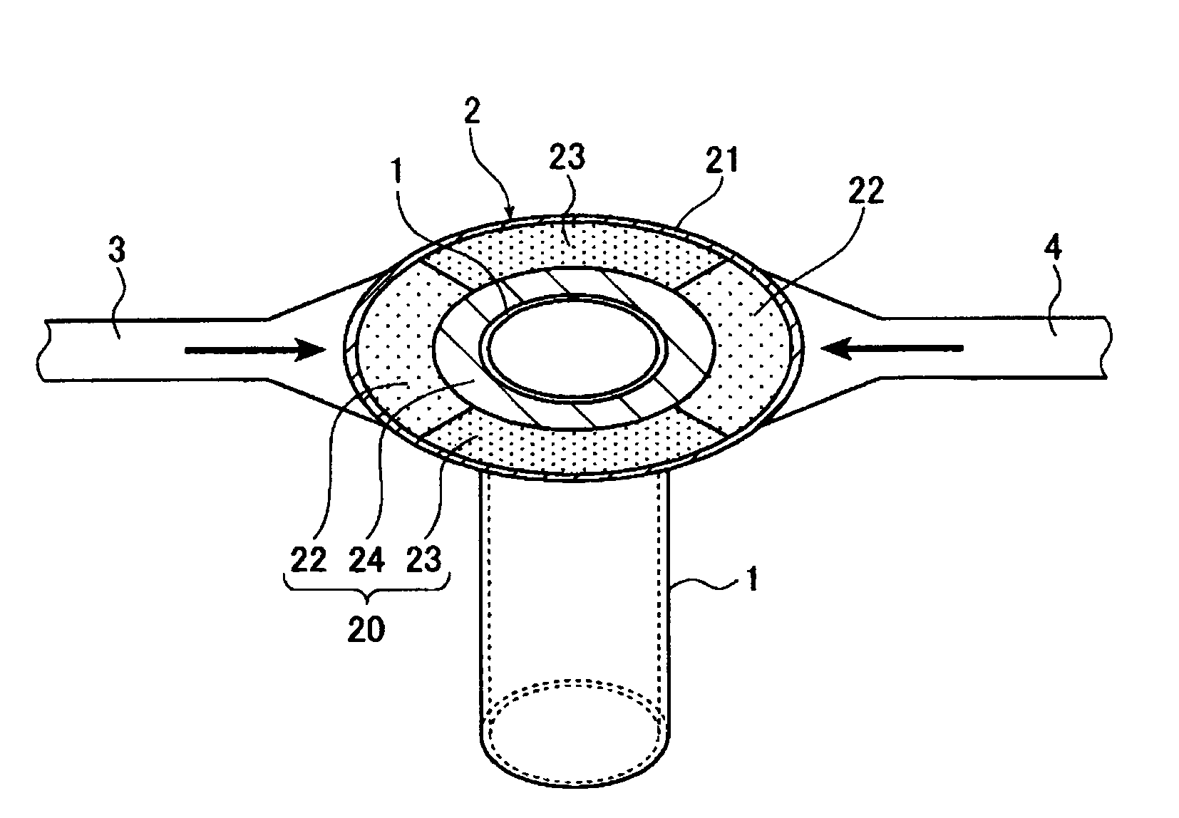
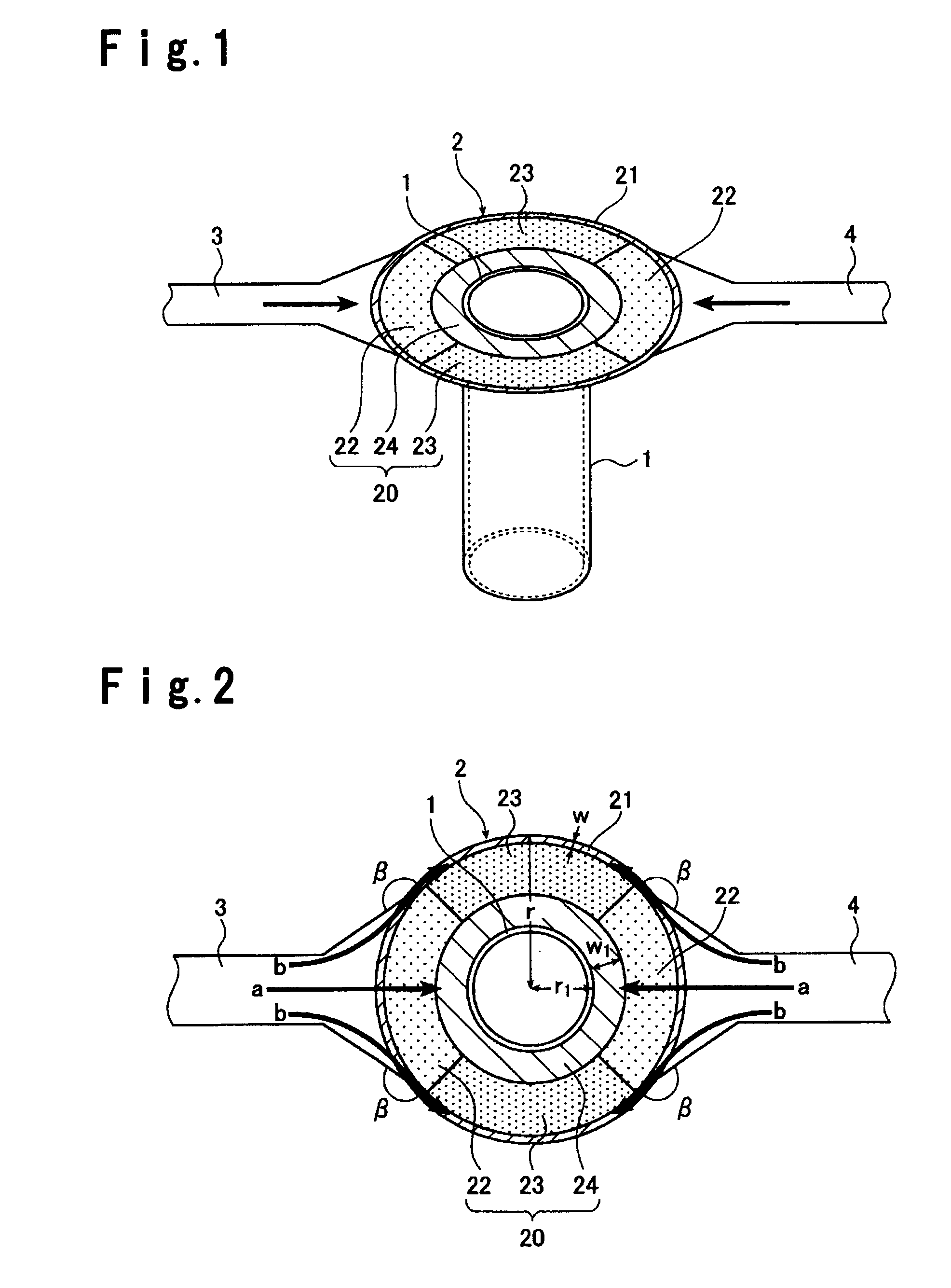
[0095]In this example, a hollow tubular body as shown in FIGS. 1 to 3 was prepared, provided that another electrode 2 having the same shape as in FIG. 2 was joined to an lower edge of the hollow tube 1 and lead-out electrodes 3, 4 were joined to this electrode 2. The structural members were joined by welding. Dimensions and constituent materials of each of the structural members are as follows.

Hollow Tube 1

[0096]Radius d: 61 mm,

[0097]length: 650 mm,

[0098]wall thickness t0: 0.5 mm and

[0099]constituent material: platinum-rhodium alloy (90% by mass of platinum and 10% by mass of rhodium)

Ring Electrode 2

[0100]Radius r: 150 mm,

[0101]width w of the thick portion 21: 10 mm,

[0102]width of the portion 22 or 23: 60 mm,

[0103]width w1 of the thin portion 24: 20 mm,

[0104]wall thickness t1 of the thick portion 21: 8 mm,

[0105]wall thickness t2 of the portion 22: 2 mm,

[0106]wall thickness t3 of the portion 23: 4 mm,

[0107]wall thickness t4 of the thin portion 24: 0.5 mm,

[0108]angle α: 110° and

[0109]...


PUM

PropertyMeasurementUnit
angleaaaaaaaaaa
angleaaaaaaaaaa
angleaaaaaaaaaa

Abstract

A hollow tubular body for molten glass by which local-overheating in the electrode for conduction heating is prevented.A hollow tubular body for molten glass by which local-overheating in the electrode for conduction heating is prevented. A hollow tubular body having a platinum or platinum alloy hollow tube, used for conduction heating is characterized in that a ring electrode is joined to the outer circumference of the hollow tube, at least one lead-out electrode is joined to an outer edge of the ring electrode, and the ring electrode comprises a core portion of electrode of platinum or platinum alloy and a thick portion of platinum or platinum alloy or of a metallic material other than platinum or platinum alloy, provided at an outer side of the core portion of electrode.

Description

BACKGROUND OF THE INVENTION[0001]1. Field of the Invention[0002]The present invention relates to a hollow tubular body having a platinum or platinum alloy hollow tube, suitable for a conduit for molten glass of a glass manufacturing apparatus, wherein an electrode for conduction heating is joined to the outer circumference of the hollow tube.[0003]The present invention relate to a method for heating the hollow tubular body of the present invention by conduction heating.[0004]The present invention relate to a glass manufacturing apparatus employing the hollow tubular body as a conduit for molten glass and a method for producing glass.[0005]2. Discussion of Background[0006]In a glass manufacturing apparatus, a hollow tube made of platinum or a platinum alloy such as a platinum-gold alloy or a platinum-rhodium alloy is employed for a conduit in which molten glass of high-temperature is passed.[0007]In a molten glass feeding apparatus described in JP-A-6-227822 for example, a platinum o...

Claims


Application Information

Patent Timeline
Patent Type & Authority Patents(United States)
IPC IPC(8): H05B6/54H05B3/60C03B7/06C03B5/225C03B7/07
CPCC03B5/2252C03B5/26C03B7/098C03B7/07C03B5/235
Inventor HIRABARA, YASUHARUITOH, HAJIME
Owner ASAHI GLASS CO LTD
Learn More