Method to reduce inrush voltage and current in a switching power converter

a switching power converter and inrush voltage technology, applied in the direction of dc-dc conversion, power supply lines, power conversion systems, etc., can solve the problems of bulky and expensive solutions, and the method is difficult to implement into a control scheme with self-oscillating pwm, so as to minimize the voltage inrush

Inactive Publication Date: 2011-09-20
INFINEON TECH AMERICAS CORP
View PDF4 Cites 11 Cited by
  • Summary
  • Abstract
  • Description
  • Claims
  • Application Information

AI Technical Summary

Benefits of technology

[0007]A circuit is provided for minimizing voltage inrush upon startup in a switching power converter having a switching stage including high and low switches connected at a common node, a feedback loop for maintaining a target output voltage, an output capacitor connected between an output node and the ground, an inductor connected between the common node and the output node, and a control IC having a first error amplifier for providing a first signal based on a comparison of a reference voltage and voltage provided by the feedback loop, the IC including a level switch connected between the ground and the common node, the level switch being controlled in accordance with the first signal, wherein a large inrush current flowing into the output capacitor when the circuit is starting up is minimized.

Problems solved by technology

However, necessity of a current sensing device which is also required for carrying rated current, makes this solution bulky and expensive.
This method is difficult to implement into a control scheme with self-oscillating PWM due to modulation index limitations.

Method used


Image

  • Method to reduce inrush voltage and current in a switching power converter
  • Method to reduce inrush voltage and current in a switching power converter
  • Method to reduce inrush voltage and current in a switching power converter

Examples


Embodiment Construction

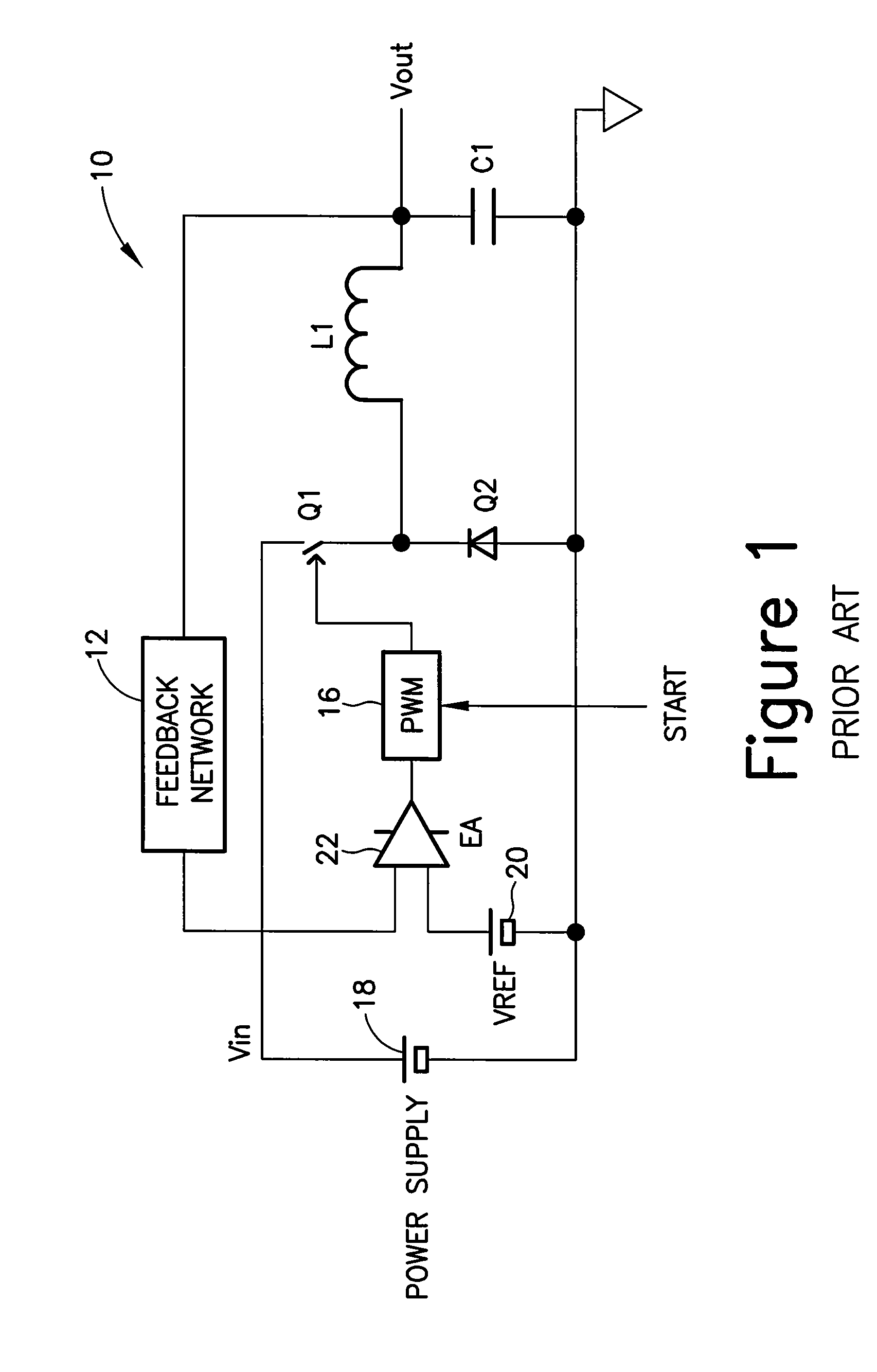
[0016]The present invention provides a pre-charging process to the output capacitor C1 without turning ON the switching device Q1. Therefore, PWM can start immediately without having an inrush current.

[0017]FIG. 3 illustrates the pre-charging circuit 30 of the present invention. The circuit 30 includes a power supply 18; a reference voltage source 20; a feedback loop 12, which usually consists of a voltage divider; at least one charging-discharging device Q3 and an error amplifier 22. The at least one charging-discharging Q3 devices is controlled by the error amplifier 22. The error amplifier 22 can be the same circuit as the one used in normal operation of the circuit 10 of FIG. 1.

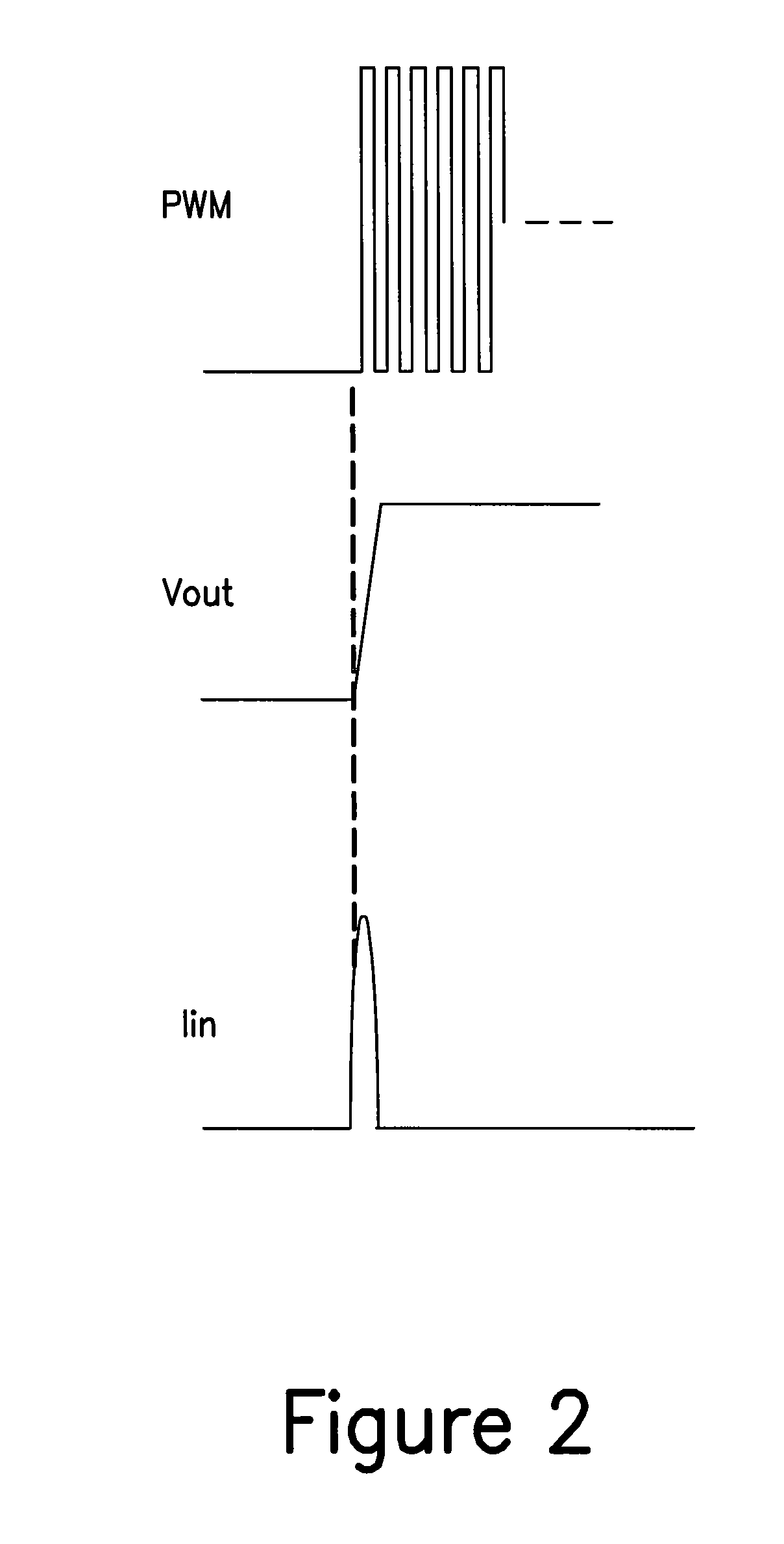
[0018]By using the same reference voltage 20 and feedback loop 12 for both pre-charging feedback loop 32 and the normal PWM operation loop 34, the target voltage of the pre-charging loop 32 can be the exactly same voltage as in the regular PWM operation. This, as illustrated in FIG. 4, results in a minimu...


PUM


Abstract

A circuit for minimizing voltage inrush upon startup in a switching power converter having a switching stage including high and low switches connected at a common node, a feedback loop for maintaining a target output voltage, an output capacitor connected between an output node and the ground, an inductor connected between the common node and the output node, and a control circuit having a first error amplifier for providing a first signal based on a comparison of a reference voltage and voltage provided by the feedback loop, the control circuit including a level switch connected between the ground and the common node, the level switch being controlled in accordance with the first signal, wherein a large inrush current flowing into the output capacitor when the circuit is starting up is minimized.

Description

CROSS-REFERENCE TO RELATED APPLICATION[0001]This application is based on and claims priority to U.S. Provisional Patent Application Ser. No. 60 / 796,734, filed on May 1, 2006 and entitled A METHOD TO REDUCE INRUSH VOLTAGE AND CURRENT IN A SWITCHING POWER CONVERTER, the entire contents of which are hereby incorporated by reference herein.BACKGROUND OF THE INVENTION[0002]The present invention relates to eliminating voltage transition causing audible click noises in Class D audio power amplifier having a single power supply and more particularly to minimizing current or voltage inrush upon startup in switching power converters.[0003]As illustrated in FIG. 1, in switching power converters 10 having a feedback loop 12 for maintaining output voltage and target output voltage other than 0V, there is a large inrush current flowing into output capacitors C1 when a switching power converter 10 is starting up. The switching power converter 10 includes a power supply 18 for providing input volta...

Claims


Application Information

Patent Timeline
Patent Type & Authority Patents(United States)
IPC IPC(8): G05F1/00
CPCH02M1/36H02M3/156Y10S323/901Y10S323/908
Inventor HONDA, JUNCHENG, XIAO-CHANG
Owner INFINEON TECH AMERICAS CORP
Why Eureka
Try Eureka