Independently calibrated wireless structural load sensor

a wireless, structural load sensor technology, applied in the direction of instruments, screws, apparatus for force/torque/work measurement, etc., can solve the problems of too expensive and difficult to maintain techniques, too expensive and difficult to monitor the operation of helicopters, and too expensive and time-consuming approaches

Inactive Publication Date: 2011-09-27
LORD CORP
View PDF40 Cites 62 Cited by
  • Summary
  • Abstract
  • Description
  • Claims
  • Application Information

AI Technical Summary

Problems solved by technology

However, this monitoring scheme has been costly and difficult to maintain for application to other fleets of aircraft.
These techniques were too costly and difficult to maintain for use on an entire fleet of helicopters.
For a fleet of aircraft, however, this approach has been too expensive and time consuming.
However, these calibration methods introduce variability based on the pilot's technique as well as variation due to strain gauge installation and manufacturing variations.
Furthermore, portions of the airframe such as the vertical tail and canopy sill are not easily loaded through proscribed flight maneuvers.

Method used


Image

  • Independently calibrated wireless structural load sensor
  • Independently calibrated wireless structural load sensor
  • Independently calibrated wireless structural load sensor

Examples


Embodiment Construction

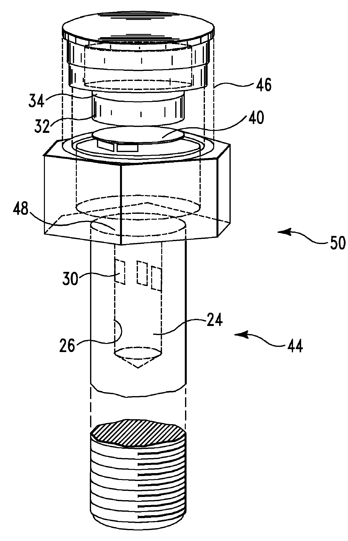
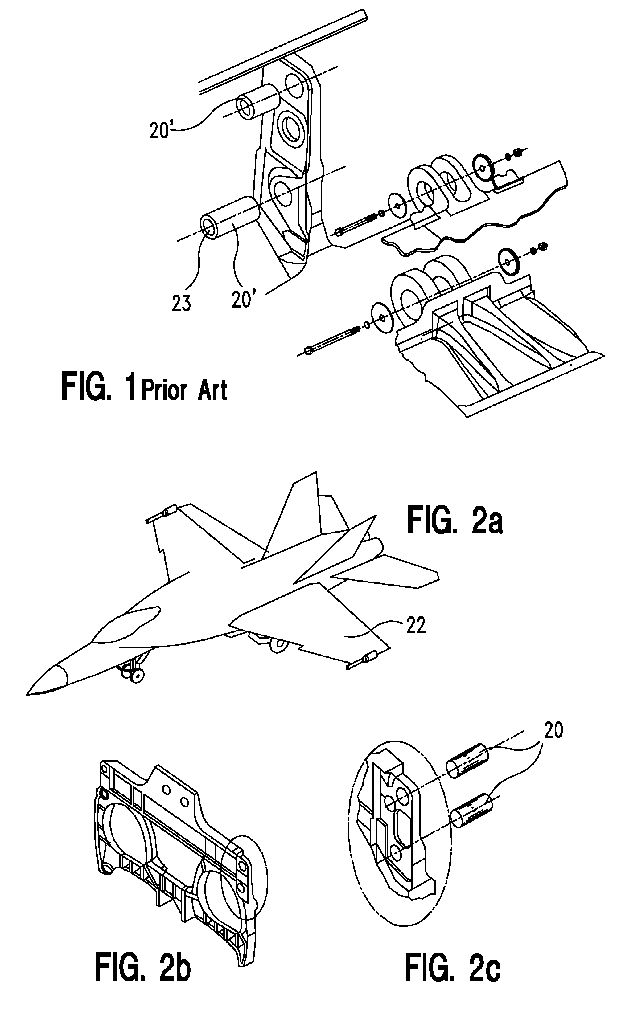
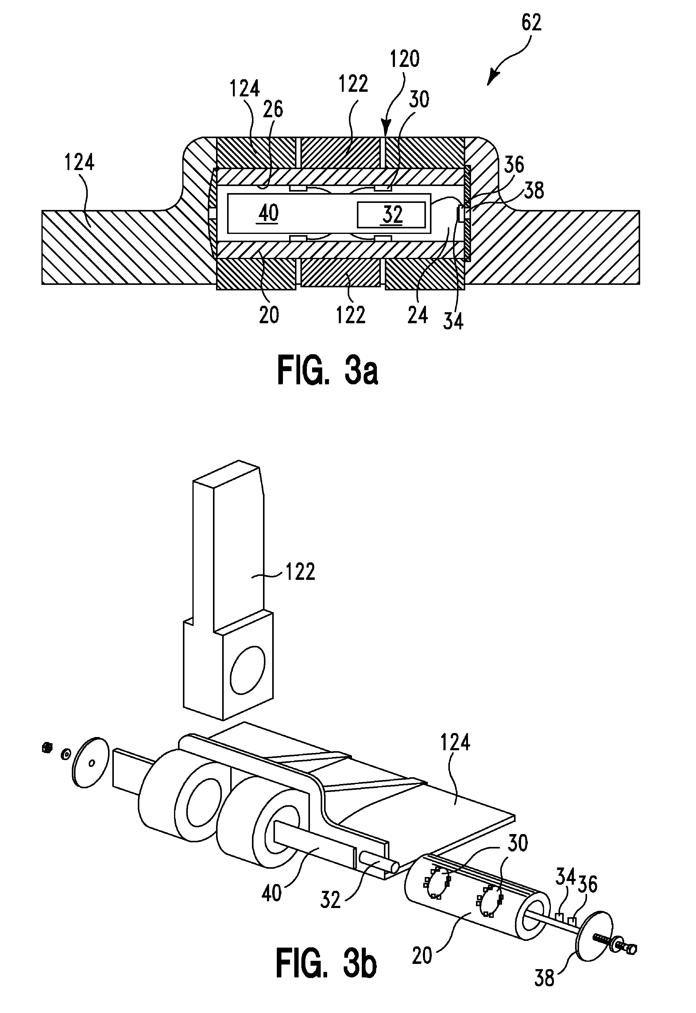
[0076]As described herein above, direct instrumentation of the frame of a structure with bonded foil strain gauges, or other hard wired sensors, has presented the problem of calibrating the entire structure in order to acquire meaningful long term in-service data. Removable load bearing elements, such as shear pins and bolts, are used extensively on fixed and rotary wing aircraft, bridges and civil structures, large machinery, ships and naval vessels. These removable load bearing elements can be instrumented with strain gauges, as described in the Kutsay patents, and with electronic components, as described in the El Bakry patent application. They may be factory calibrated independent of the structure to which they are mounted to perform load monitoring for structural health monitoring.

[0077]In one embodiment, existing standard shear pins 20′ in shear joints on existing structures are replaced with instrumented shear pins 20 to provide structural load information on the existing str...


PUM


Abstract

A device includes a removable load element. The removable load element includes a pin portion and a housing portion. The pin portion extends from the housing portion. The pin portion includes a sensor. The housing portion includes an electronic circuit connected to the sensor.

Description

RELATED PATENT APPLICATIONS AND PRIORITY[0001]This application claims priority of Provisional Patent Application 61 / 062,140, filed Jan. 24, 2008, incorporated herein by reference.[0002]This application is also related to the following patents and patent applications, all of which are incorporated herein by reference:[0003]1. U.S. Pat. No. 3,695,096 Strain detecting load cell[0004]2. U.S. Pat. No. 4,283,941 Double shear beam strain gauge load cell[0005]3. U.S. Pat. No. 4,364,280 Double shear beam strain gauge load cell[0006]4. U.S. Pat. No. 7,188,535 Load cell having strain gauges of arbitrary location[0007]5. U.S. Pat. No. 6,629,446 Single vector calibration system for multi-axis load cells and method for calibrating a multi-axis load cell[0008]6. U.S. Pat. No. 7,170,201 Energy harvesting for wireless sensor operation and data transmission[0009]7. U.S. Pat. No. 7,081,693 Energy harvesting for wireless sensor operation and data transmission[0010]8. U.S. Pat. No. 7,143,004 Solid state...

Claims


Application Information

Patent Timeline
Patent Type & Authority Patents(United States)
IPC IPC(8): G01B7/16F16B31/02
CPCG01L1/2225G01L5/0004G01L5/161G01L5/24G01L5/1627
Inventor ARMS, STEVEN WTOWNSEND, CHRISTOPHER P.CHURCHILL, DAVID L.
Owner LORD CORP
Why Eureka
Try Eureka