Flow cell for chemiluminescence analysis

a flow cell and flow cell technology, applied in the field of flow cells for chemiluminescence analysis, can solve the problems of light loss in the tubing wall, inability or easy to achieve, and other flow paths such as reversing turns which enhance mixing,

Inactive Publication Date: 2011-10-04
GLOBAL FIA
View PDF10 Cites 13 Cited by
  • Summary
  • Abstract
  • Description
  • Claims
  • Application Information

AI Technical Summary

Benefits of technology

[0019]In a second aspect, the invention provides an improvement in a flow cell for use with flow-based chemiluminescence measurements. The improvement comprises using a plate with grooves, the plate having a pair of converging inlet ports near the center of the plate, to provide a mechanism for mixing a sample and a reagent, thereby effecting immediate generation of chemiluminescence in the path of means for measuring chemiluminescence emitted from the flow cell.

Problems solved by technology

Other flow paths, such as reversing turns which enhance mixing, are not possible or easily achieved.
Hence, some light is lost in the tubing walls.(d) Tubing has a curved wall, which causes light loss due to reflection, compared with a flat wall.(e) The internal diameter of the channel is limited by the availability of tubing sizes.

Method used


Image

  • Flow cell for chemiluminescence analysis
  • Flow cell for chemiluminescence analysis
  • Flow cell for chemiluminescence analysis

Examples


Embodiment Construction

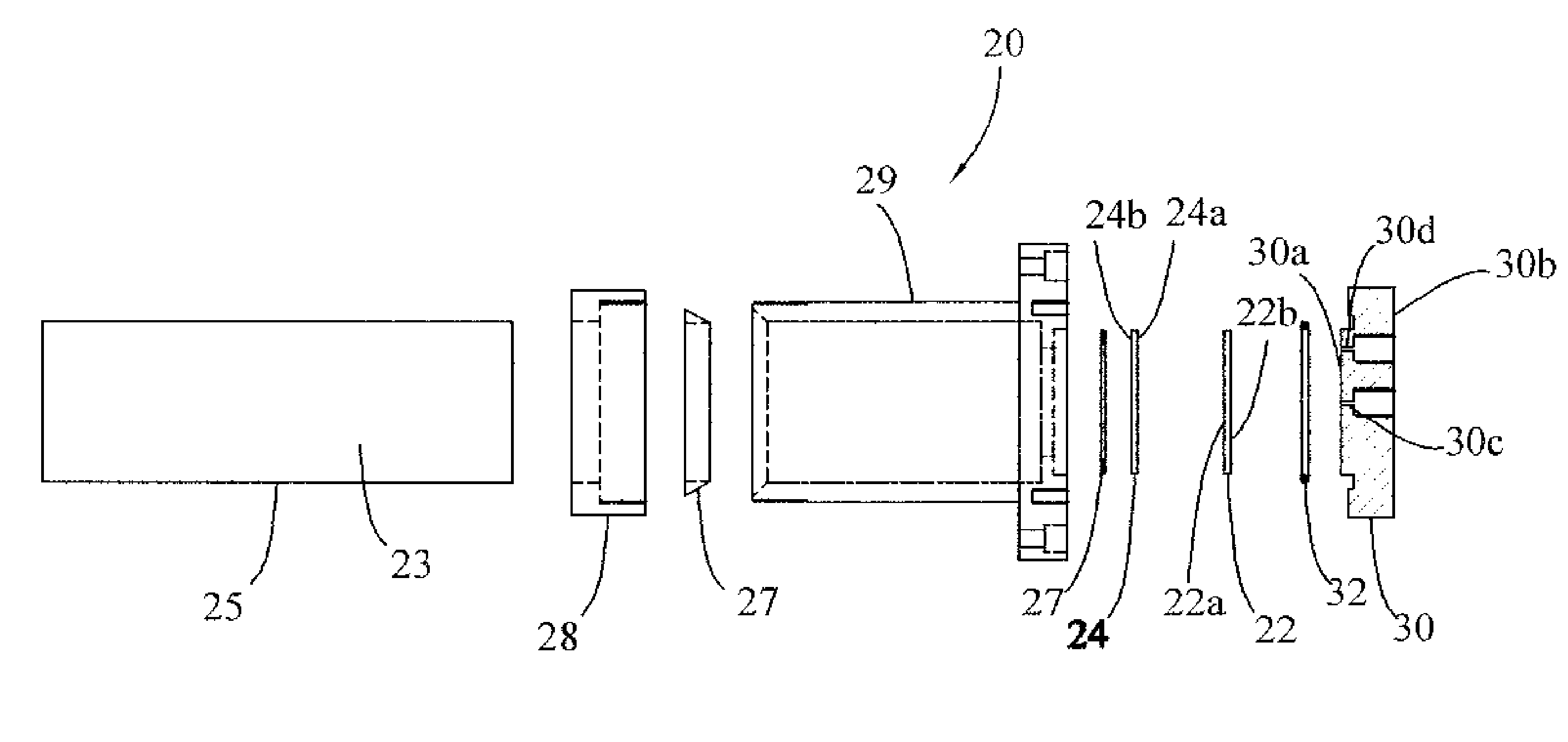
[0025]More specifically, reference is made to FIG. 4, in which is shown a flow cell for chemiluminescence analysis, made in accordance with the principles of the present invention, and generally designated by the numeral 20.

[0026]The flow cell 20 comprises a flat, thin plate 22 having first and second opposite faces 22a and 22b. There is a flat sapphire window 24 having first and second opposite faces 24a and 24b. In lieu of the sapphire window, quartz, glass, or other acceptable materials may be employed. By “acceptable” is meant “maximally transparent in wavelength range of emission of the emitted light and chemically resistant to the reagents used”. An example would be emitted radiation in the “visible” region of the light spectrum. Sapphire, quartz and glass would all be acceptable. However, with emitted radiation in the “ultraviolet” spectral region, glass would no longer be acceptable, due to limited light transmission. A light detector 23 such as a circular photomultiplier, p...


PUM

PropertyMeasurementUnit
chemiluminescenceaaaaaaaaaa
flow-based chemiluminescenceaaaaaaaaaa
Chemiluminescenceaaaaaaaaaa

Abstract

A flow cell for chemiluminescence analysis. The flow cell has a flat, thin, opaque plate, with a groove machined into one side of the plate. An inlet port at the center, and an outlet port at the outside end of the groove pass through the plate, which is sandwiched between a flat sapphire window and a cell cap of a housing. The groove side faces the sapphire window, forming a flow channel with one wall being the sapphire window. A light detector is inserted into the housing until it butts up against that part of the housing holding the sapphire window, placing it very close to the generated light. The other side of the plate mates with inlet and outlet ports of the housing cap.

Description

BACKGROUND OF THE INVENTION[0001]The present invention relates to chemical analysis. More particularly, the invention relates to a flow cell for use with flow-based chemiluminescence measurements.[0002]Chemiluminescence is the generation of light from chemical reactions. Chemiluminescence processes have attracted mankind's attention for centuries. Aristotle wrote the first known report on the phenomenon when he noted that weak light was emitted by dead fish and fungi. The term chemiluminescence was first defined by Wiedemann in 1888 as light emitted from chemical reactions.[0003]Many chemiluminescence reactions are now well known. Early studies of chemiluminescence focused primarily on the chemistry and mechanisms of chemiluminescence reactions. In the early 1960's, analytical applications of chemiluminescence reactions began to appear in the literature. Since then, chemiluminescence analytical methods have grown substantially, due to the advantages of low detection limits, wide lin...

Claims


Application Information

Patent Timeline
Patent Type & Authority Patents(United States)
IPC IPC(8): G01N21/76G01N21/00G01N21/64G01T1/10
CPCG01N21/05G01N21/76G01N2021/0346
Inventor OLSON, DON C.WOLCOTT, DUANE K.MARSHALL, GRAHAM D.
Owner GLOBAL FIA
Why Eureka
Try Eureka