Motor drive circuit

a technology of motor drive and drive circuit, which is applied in the direction of motor/generator/converter stopper, electronic commutator, dynamo-electric converter control, etc., can solve the problems of increased noise, increased consumption current, and increased noise when the fan motor is driving

Active Publication Date: 2011-10-04
SEMICON COMPONENTS IND LLC
View PDF13 Cites 2 Cited by
  • Summary
  • Abstract
  • Description
  • Claims
  • Application Information

AI Technical Summary

Benefits of technology

[0009]A motor drive circuit according to an aspect of the present invention, comprises: a first amplifier circuit configured to amplify a difference between first and second position detection signals with a gain becoming smaller according to drop in power supply voltage, to output a first amplification signal, the first and second position detection signals being signals indicating a rotational position of a rotor in a motor, having a frequency corresponding to a rotation speed of the motor, and being opposite in phase to each other; a second amplifier circuit configured to amplify the difference between the first position detection signal and the second position detection signal with the gain, to output a second amplification signal opposite in phase to the first amplification signal; and a drive circuit configured to amplify the difference between the first amplification signal and the second amplification signal with a predetermined gain so as to be saturated at the power supply voltage, to output a driving voltage for driving the motor.

Problems solved by technology

Therefore, when the power supply voltage VDD is low, the driving voltage VOUT1 gets close to a square wave, and the noise when the fan motor is driving is increased.
If the proportion of the rise time and fall time in the driving voltage VOUT1 is changed according to change of the power supply voltage VDD as above, problems occur such as increase in noise and increase in consumption current.

Method used


Image

  • Motor drive circuit
  • Motor drive circuit
  • Motor drive circuit

Examples


Embodiment Construction

[0017]At least the following details will become apparent from descriptions of this specification and of the accompanying drawings.

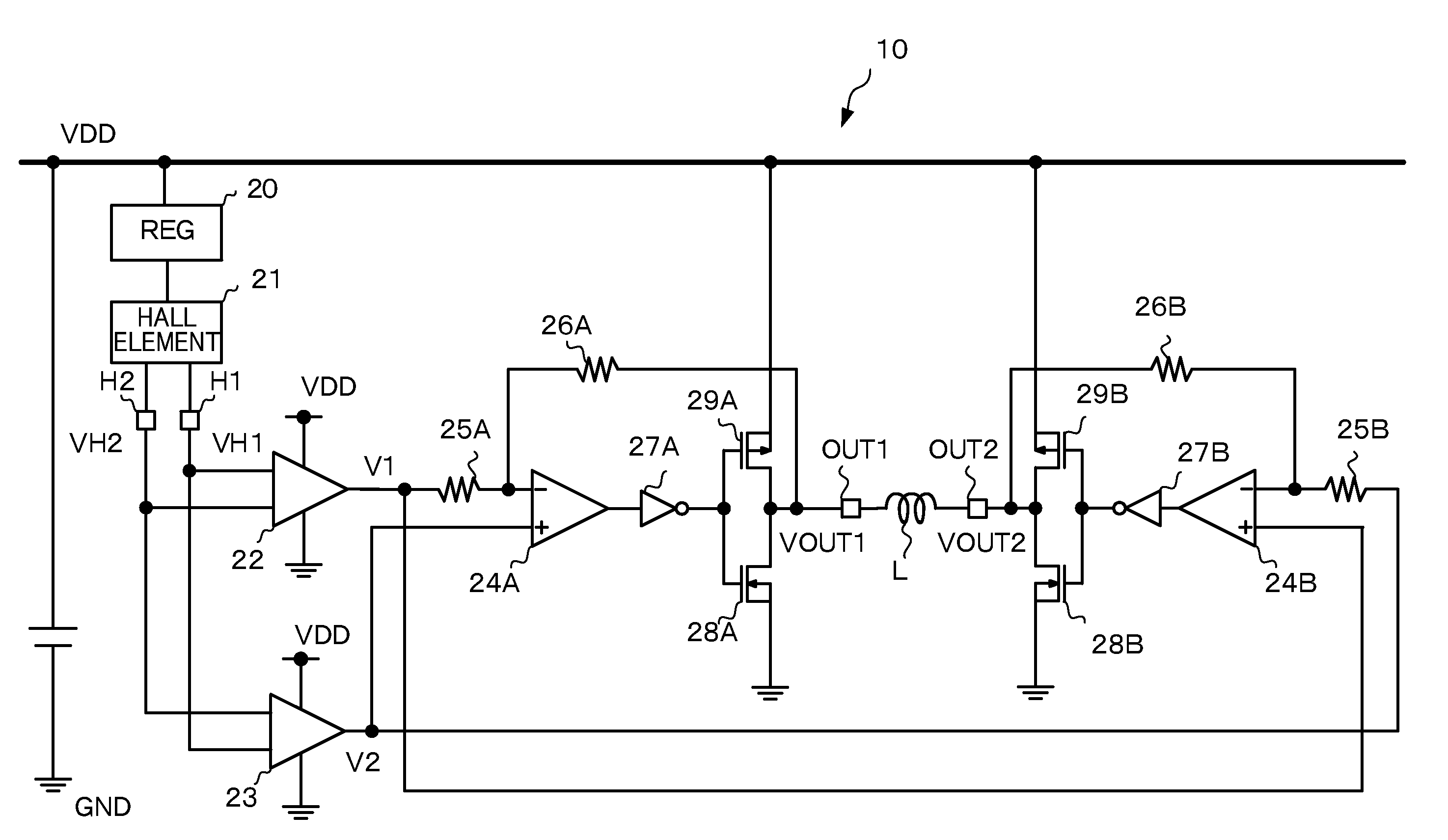
[0018]FIG. 1 is a diagram illustrating a configuration of a motor drive circuit 10 according to an embodiment of the present invention. The motor drive circuit 10 is, in electronic equipment such as a notebook computer, for example, incorporated in a fan motor for cooling a heat-producing component such as a processor and is used for driving a motor for rotating a fan for cooling.

[0019]The motor drive circuit 10 according to an embodiment of the present invention is a circuit for driving a single-phase fan motor so as to become at a rotation speed according to a level of a power supply voltage VDD, and includes amplifier circuits 22, 23, operational amplifiers 24A, 24B, resistors 25A, 25B, 26A, 26B, inverters 27A, 27B, NMOS transistors 28A, 28B, and PMOS transistors 29A, 29B. In an embodiment according to the present invention, the motor drive circuit 10...


PUM


Abstract

A motor drive circuit includes a first amplifier circuit to amplify a difference between first and second position detection signals with a gain becoming smaller according to drop in power supply voltage, to output a first amplification signal, the first and second position detection signals being signals indicating a rotational position of a rotor in a motor, having a frequency corresponding to a rotation speed of the motor, and being opposite in phase to each other; a second amplifier circuit to amplify the difference between the first and second position detection signals with the gain, to output a second amplification signal opposite in phase to the first amplification signal; and a drive circuit to amplify the difference between the first amplification signal and the second amplification signal with a predetermined gain to be saturated at the power supply voltage, to output a driving voltage for driving the motor.

Description

CROSS-REFERENCE TO RELATED APPLICATION[0001]This application claims the benefit of priority to Japanese Patent Application No. 2008-162235, filed Jun. 20, 2008, of which full contents are incorporated herein by reference.BACKGROUND OF THE INVENTION[0002]1. Field of the Invention[0003]The present invention relates to a motor drive circuit.[0004]2. Description of the Related Art[0005]In electronic equipment such as a notebook computer, a fan motor is used for cooling a heat-producing component such as a processor. When driving the fan motor, there may be employed a motor drive circuit that gradually changes a driving voltage of a motor coil in order to reduce noise in the fan motor (See Japanese Patent Laid-Open Publication No. 2004-166379, for example.)[0006]FIG. 4 is a diagram illustrating an example of a configuration of a motor drive circuit for driving a single-phase fan motor. A motor drive circuit 100 controls driving voltages VOUT1 and VOUT2 for driving a motor coil L accordin...

Claims


Application Information

Patent Timeline
Patent Type & Authority Patents(United States)
IPC IPC(8): H02P6/16H02P6/06H02P6/08H02P6/26
CPCH02P6/06
Inventor IMAI, TOSHIYUKIIIDA, TAKAHIRONOIE, JOJI
Owner SEMICON COMPONENTS IND LLC
Why Eureka
Try Eureka