Display driver and electronic instrument

a technology of display driver and electronic instrument, applied in the direction of instruments, static indicating devices, baseband system details, etc., can solve the problem that the sub display driver cannot receive data

Inactive Publication Date: 2011-10-04
SEIKO EPSON CORP
View PDF14 Cites 39 Cited by
  • Summary
  • Abstract
  • Description
  • Claims
  • Application Information

AI Technical Summary

Benefits of technology

[0027]The invention may provide a display driver which enables efficient control of a sub display driver which drives a sub display panel, and an electronic instrument including the same.

Problems solved by technology

Therefore, if the data transferred from the host device through the high-speed serial bus is directly output to the sub display driver, there may be a case where the sub display driver cannot receive the data.

Method used


Image

  • Display driver and electronic instrument
  • Display driver and electronic instrument
  • Display driver and electronic instrument

Examples


Embodiment Construction

[0027]The invention may provide a display driver which enables efficient control of a sub display driver which drives a sub display panel, and an electronic instrument including the same.

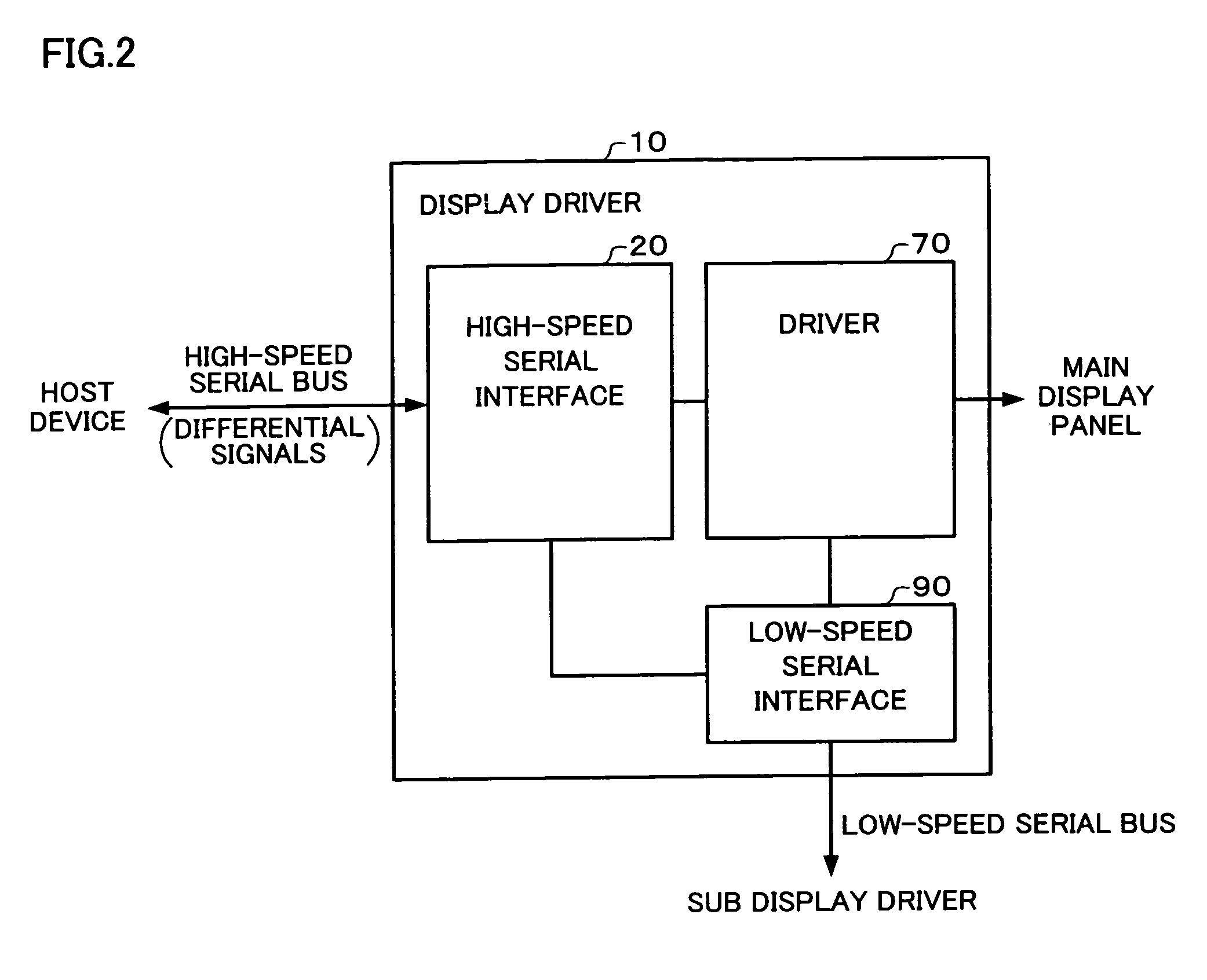
[0028]One embodiment of the invention provides a display driver comprising:

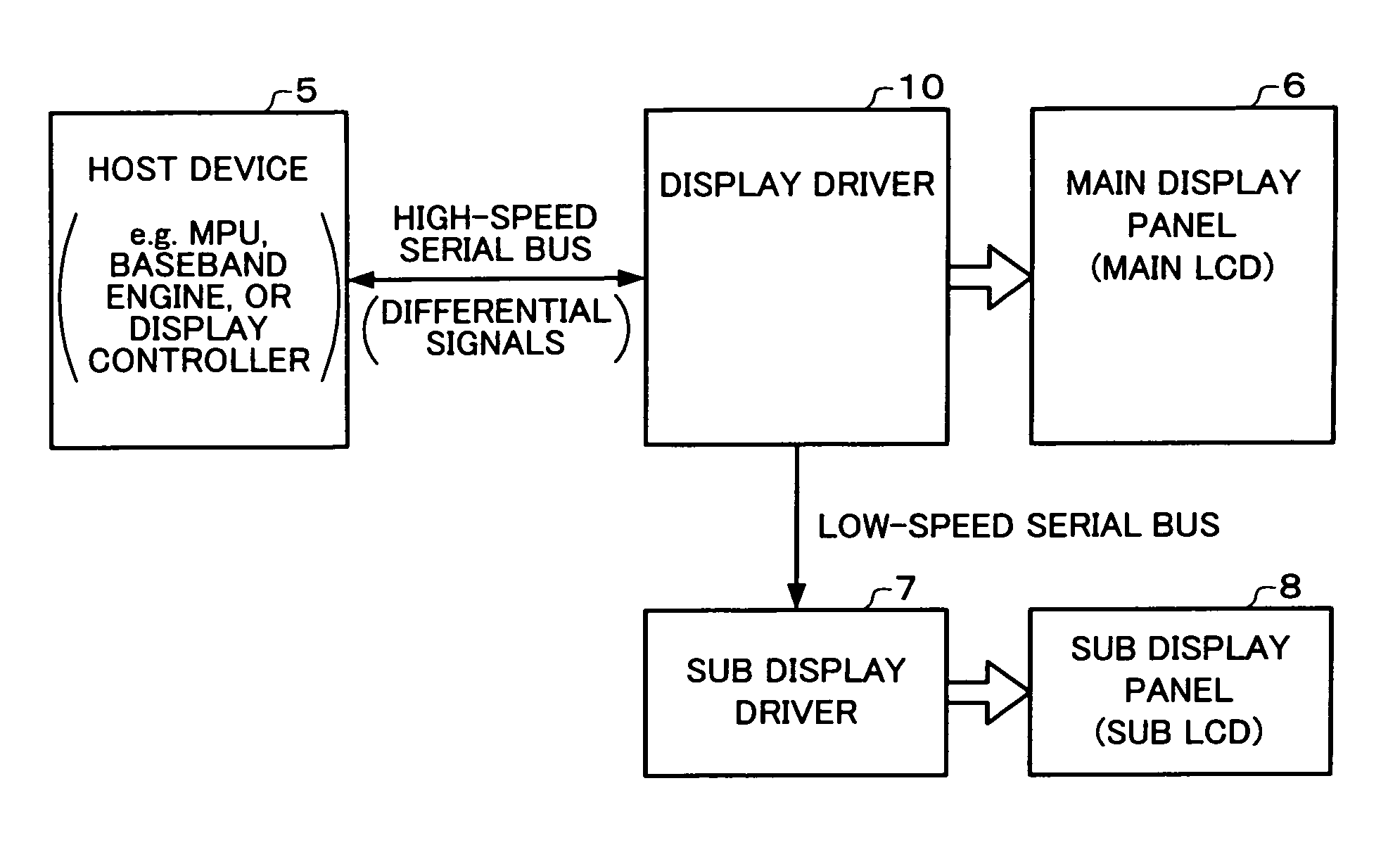
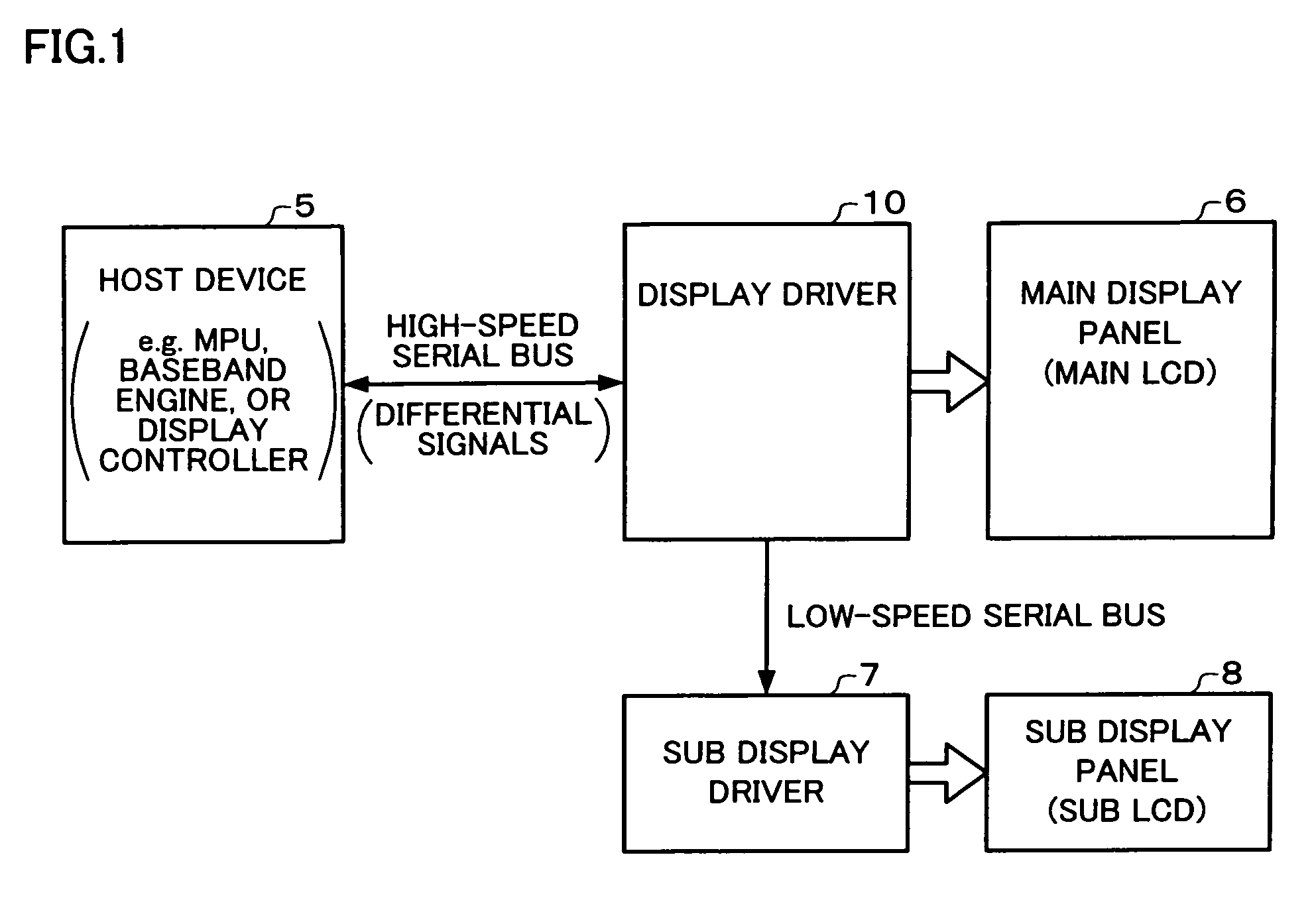
[0029]a high-speed serial interface circuit which receives a packet from a host device through a high-speed serial bus using differential signals, and outputs a command or data included in the received packet;

[0030]a driver circuit which drives a main display panel based on the command or the data output from the high-speed serial interface circuit; and

[0031]a low-speed serial interface circuit which outputs a sub display driver command or data to a sub display driver through a low-speed serial bus of which a transfer rate is lower than a transfer rate of the high-speed serial bus when the packet received from the host device includes the sub display driver command or data.

[0032]According to one embodiment of the invention, t...


PUM


Abstract

A display driver comprising: a high-speed serial interface circuit which receives a packet from a host device through a high-speed serial bus using differential signals, and outputs a command or data included in the received packet; a driver circuit which drives a main display panel based on the output command or data; and a low-speed serial interface circuit which outputs a command or data to a sub display driver through a low-speed serial bus when the packet received from the host device includes the sub display driver command or data. And the display driver inserts dummy data to the packet to adjust the difference of the transfer rate by inserting a dummy the dummy data. And the display driver adjust the difference of the transfer rate.

Description

[0001]Japanese Patent Application No. 2005-92114, filed on Mar. 28, 2005, is hereby incorporated by reference in its entirety.BACKGROUND OF THE INVENTION[0002]The present invention relates to a display driver and an electronic instrument.[0003]In recent years, a high-speed serial transfer interface such as a low voltage differential signaling (LVDS) interface has attracted attention as an interface aiming at reducing EMI noise or the like. In such a high-speed serial transfer, data is transferred by causing a transmitter circuit to transmit serialized data using differential signals and causing a receiver circuit to differentially amplify the differential signals (JP-A-2001-222249).[0004]An ordinary portable telephone includes a first instrument section provided with buttons for inputting a telephone number or a character, a second instrument section provided with a main liquid crystal display (LCD), a sub LCD, or a camera, and a connection section (e.g. hinge) which connects the fi...

Claims


Application Information

Patent Timeline
Patent Type & Authority Patents(United States)
IPC IPC(8): G09G5/00
CPCG06F3/1431H04L25/0272H04L25/05E06B3/5454E06B3/62E06B3/64
Inventor TAMURA, TSUYOSHI
Owner SEIKO EPSON CORP
Why Eureka
Try Eureka