Power supply circuit and power supply system

a power supply circuit and self-oscillation technology, applied in the direction of electric variable regulation, process and machine control, instruments, etc., can solve the problems of increasing power loss, increasing noise, and excessive draining to source voltage of fetb>1/b>, so as to reduce the energy stored in the resonance section, the effect of quick turning off the first switching element and on-period of the first switching elemen

Inactive Publication Date: 2011-10-04
MATSUSHITA ELECTRIC WORKS LTD
View PDF20 Cites 8 Cited by
  • Summary
  • Abstract
  • Description
  • Claims
  • Application Information

AI Technical Summary

Benefits of technology

[0013]According to this configuration, there is provided a first charging section including a diode for inhibiting the flow of current toward the feedback coil from the turn-off capacitor, and a zener diode which operates when the voltage of the feedback coil exceeds a fixed value, between the feedback coil and the turn-off capacitor. As the result of this, when a large voltage is outputted from the power supply section, the voltage of the feedback coil exceeds a fixed value and the first charging section operates thereby supplying current to the turn-off capacitor. This will enable that the turn-off capacitor is charged with an on-current of the first switching element and a current supplied from the first charging section during an on-period of the first switching element, to quickly turn on the second switching element and quickly turn off the first switching element. As a result, the on-period of the first switching element is decreased thereby reducing the energy stored in the resonance section, enabling to suppress the increase of the output current to be passed through the load device. By this configuration, an output characteristic, which indicates the relationship between the voltage outputted from the power supply section and the output current passed through the load device when the output voltage represented by the abscissa axis and the output current represented by the ordinate axis, becomes flat thus enabling to provide a worldwide applicable power supply circuit.
[0014]Further, since when the voltage outputted from the power supply section is high, the turn-off capacitor will be quickly charged by the operation of the first charging section, the on-period of the first switching element decreases thus enabling to prevent an excessive voltage from being applied to the first switching element.
[0015]Further, since the first charging section comprises a diode for inhibiting the current from flowing from the turn-off capacitor toward the feedback coil, the charge quantity to be stored in the turn-off capacitor when the first switching element turns on is made to be constant and thereby the charging time of the turn-off capacitor becomes constant, enabling to maintain the on-period of the first switching element to be constant thereby supplying stable power to the load device.

Problems solved by technology

However, since the power supply apparatus in Patent Document 1 is not configured to be worldwide applicable, when it is used in the countries or regions where the voltage of the power supply section E0 is large, the drain-to-source voltage of the FET1 becomes excessively large, which leads to a problem that an FET1 having a large drain-to-source withstand voltage needs to be adopted as the FET1.
On the other hand, since the switching power supply apparatus of Patent Document 2 is an RCC type, its switching element operates in a hard switching mode and, as the result of that, a problem arises in that more noise will be generated and the loss of power will increase.

Method used


Image

  • Power supply circuit and power supply system
  • Power supply circuit and power supply system
  • Power supply circuit and power supply system

Examples


embodiment 1

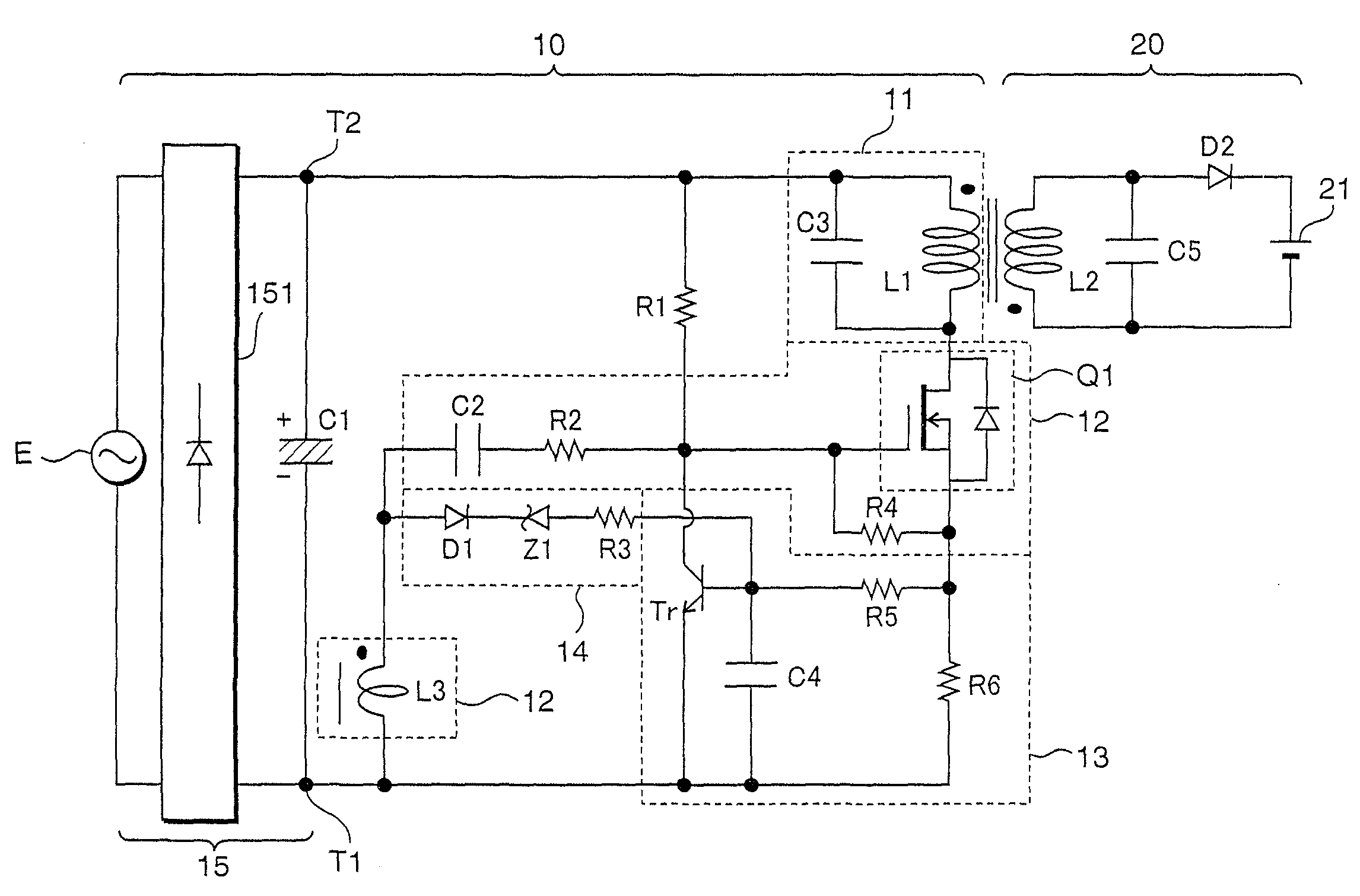
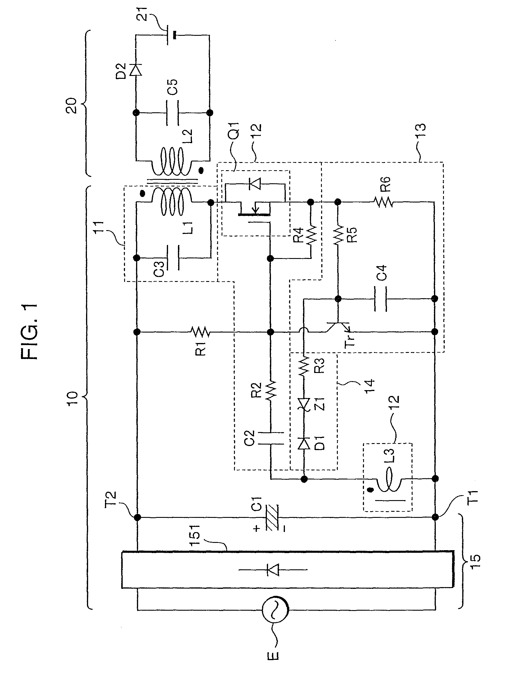
[0034]FIG. 1 shows a circuit diagram of the power supply system according to Embodiment 1 of the present invention. The power supply system comprises a power supply circuit 10 and a load device 20. The power supply circuit 10 comprises a resonance section 11, an oscillation section 12, a turn-off section 13, a charging section 14 (first charging section), and a power supply section 15.

[0035]The resonance section 11 comprises a resonance coil L1 and a resonance capacitor C3, which are connected in parallel, and supplies power to the load device.

[0036]The resonance section 12 comprises a feedback coil L3, a capacitor C2, a resistor R2, and a transistor Q1 (first switching element), and a resistor R4, and causes the resonance section 11 to self oscillate. The feedback coil L3 is magnetically coupled with the resonance coil L1 so that the gate side terminal of the transistor Q1 has positive polarity. Hereafter, the gate side terminal of the transistor Q1 of the feedback coil L3 is refer...

embodiment 2

[0061]Next, the power supply system according to Embodiment 2 of the present invention will be described. FIG. 4 shows a circuit diagram of the power supply system according to Embodiment 2 of the present invention. In is noted that in FIG. 4, like parts of those of Embodiment 1 are given like reference characters and the description thereof will be omitted. The power supply system according to Embodiment 2 is characterized in that a resistor R7 is connected between the positive electrode T2 and the base of the turn-off transistor Tr.

[0062]Since voltage inputted from the commercial power supply E will cause a current to flow in the turn-off capacitor C4 via the resistor R7, a partial voltage between the resistor R7 and the combined resistor of resistors R5 and R6 is always outputted to the turn-off capacitor C4. Accordingly, as the voltage of the commercial power supply E increases, the voltage outputted to the turn-off capacitor C4 will increase, thus enabling that the on-period of...

embodiment 3

[0065]Next, the power supply system according to Embodiment 3 of the present invention will be described. FIG. 5 shows a circuit diagram of the power supply system according to Embodiment 3 of the present invention. In is noted that in FIG. 5, like parts of those of Embodiments 1 and 2 are given like reference characters and the description thereof will be omitted. The power supply system according to Embodiment 3 is characterized in that a smoothing section 16 is connected in parallel to the charging section 14 in the power supply system of Embodiment 1. The smoothing section 16 comprises a diode D3, a capacitor C7, and a resistor R8. The diode D3 is connected at its anode to the positive terminal of the feedback coil L3 and at its cathode to the base of the turn-off transistor Tr via the resistor R8 and to the negative electrode T1 via the capacitor C7.

[0066]The smoothing section 16 performs the smoothing of the voltage of the feedback coil L3 to generate a voltage corresponding t...


PUM


Abstract

To provide a power supply circuit which can be applied worldwide without using a high withstand voltage switching element and can supply a load device with stable power. A charging section is arranged between a turn-off capacitor and a load coil. The charging section has the anode connected to the positive terminal of a feedback coil and the cathode connected to the cathode of a zener diode. Thus, when a voltage of a commercial power supply is high, the charging section operates, the turn-off capacitor is quickly charged, an on-period of a transistor is shortened, and an excessive voltage is prevented from being applied between the drain and the source of the transistor. At the same time, an output characteristic indicating relationship between the voltage of the commercial power supply and a current flowing in the load device is permitted to be flat.

Description

TECHNICAL FIELD[0001]The present invention relates to a self-oscillation type power supply circuit and a power supply system.BACKGROUND ART[0002]As overseas traveling has become more prevalent in recent years, there is a strong demand for the development of a power supply apparatus which can be used not only within the country but also in foreign countries where the voltage of the commercial power supply is different from that in the country, that is, a power supply which can be applied worldwide for charging appliances such as shavers, electric tooth brushes, and the like.[0003]FIG. 17 is a circuit diagram to show a conventional power supply apparatus described in Patent Document 1. The power supply apparatus shown in FIG. 17 is a self-oscillation type power supply apparatus which operates as described below. First, when a power supply section E0 is connected, power is supplied to a capacitor C20 via a bias resistor R80 so that the capacitor C20 is charged and the gate voltage VG o...

Claims


Application Information

Patent Timeline
Patent Type & Authority Patents(United States)
IPC IPC(8): H02M3/335H02M1/10
CPCH02M3/3385H02M2001/0058Y02B70/1491Y02B70/10H02M1/0058H02M3/28H02M3/338
Inventor KITAMURA, HIROYASUYAMASHITA, MIKIHIROIWAO, SEIICHI
Owner MATSUSHITA ELECTRIC WORKS LTD
Why Eureka
Try Eureka