Apparatus for preventing ice accretion

a technology of ice accretion and apparatus, which is applied in the direction of liquid fuel engines, marine propulsion, vessel construction, etc., can solve the problems of reducing lift, increasing drag, affecting the performance of the component, so as to prevent ice accretion

Inactive Publication Date: 2011-10-11
ROLLS ROYCE PLC
View PDF11 Cites 16 Cited by
  • Summary
  • Abstract
  • Description
  • Claims
  • Application Information

AI Technical Summary

Benefits of technology

[0009]It is an object of this invention to provide an apparatus for preventing ice accretion on a component, without the need for any additional system or external energy supply. The

Problems solved by technology

Ice tends to form first on the leading edges of components, altering the airflow, reducing lift, increasing drag and adding weight.
Additionally, damage may result from ice breaking away and being ingested into the engine or hitting the acoustic material lining the intake duct.
A disadvantage of known anti-icing and de-icing systems is that they require additional hardware, in the form of bleeds and ducting for hot air, or heating elements and their associated control systems, which add weight and complexity to the engine.
In addition, the need for warmed and pressurised air, or for electrical power, is detrimental to the overall performance of the engine and reduces its efficiency.
Many components of

Method used


Image

  • Apparatus for preventing ice accretion
  • Apparatus for preventing ice accretion
  • Apparatus for preventing ice accretion

Examples


second embodiment

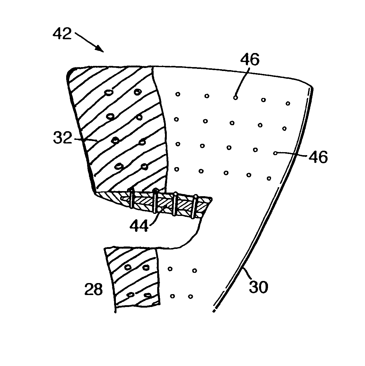
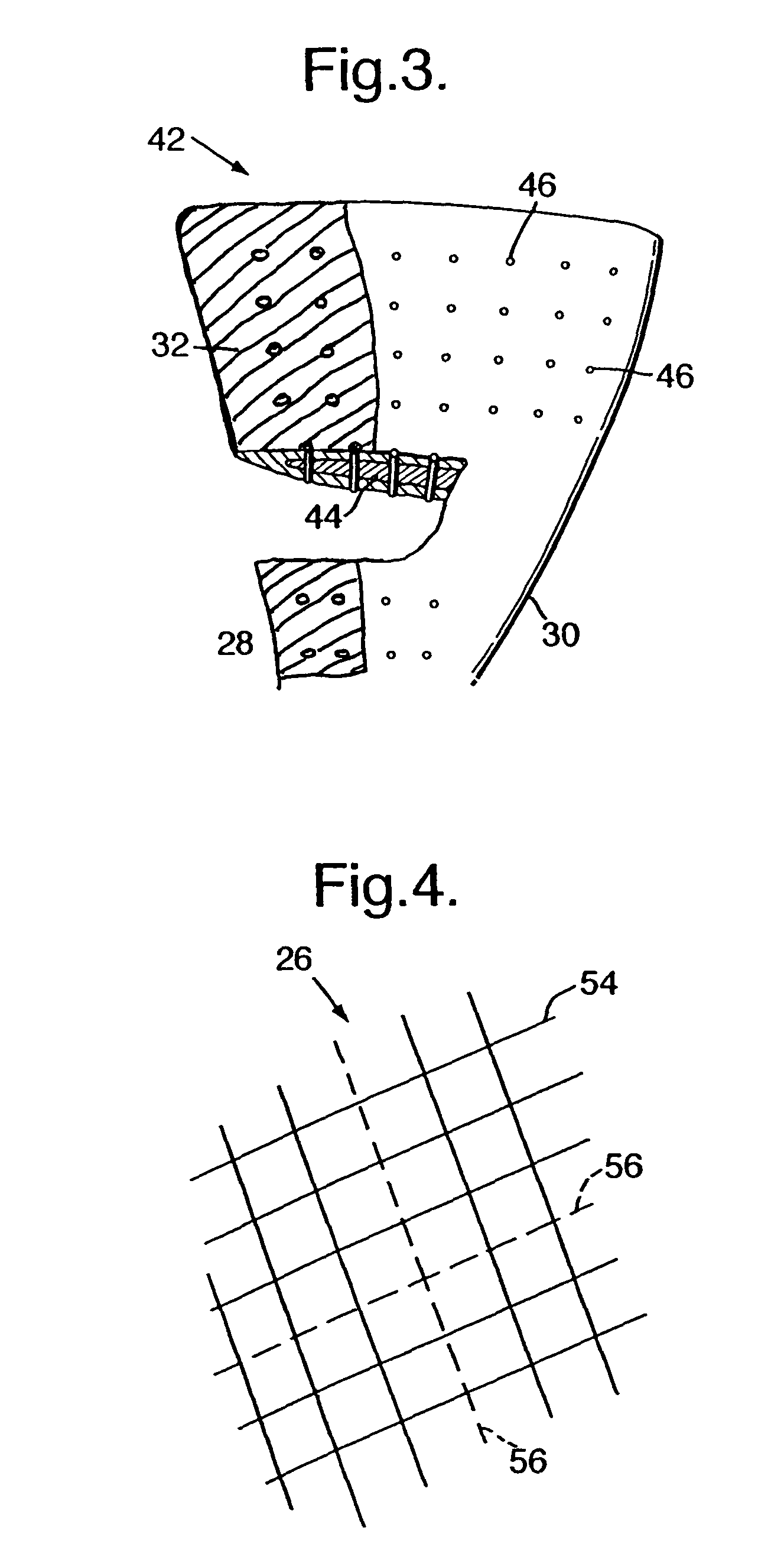
[0023]A second embodiment is shown in FIG. 3. Here, the viscoelastic material, a synthetic mix of epoxy and polyurethane, is provided as a filler 44 for a hollow composite blade 42. Pins 46 of carbon fibre provide a heat conduction path from the viscoelastic filler 44 to the surface of the blade 42, and also add mechanical strength. The number and positions of these pins 46 may be arranged to optimise the heat transfer.

third embodiment

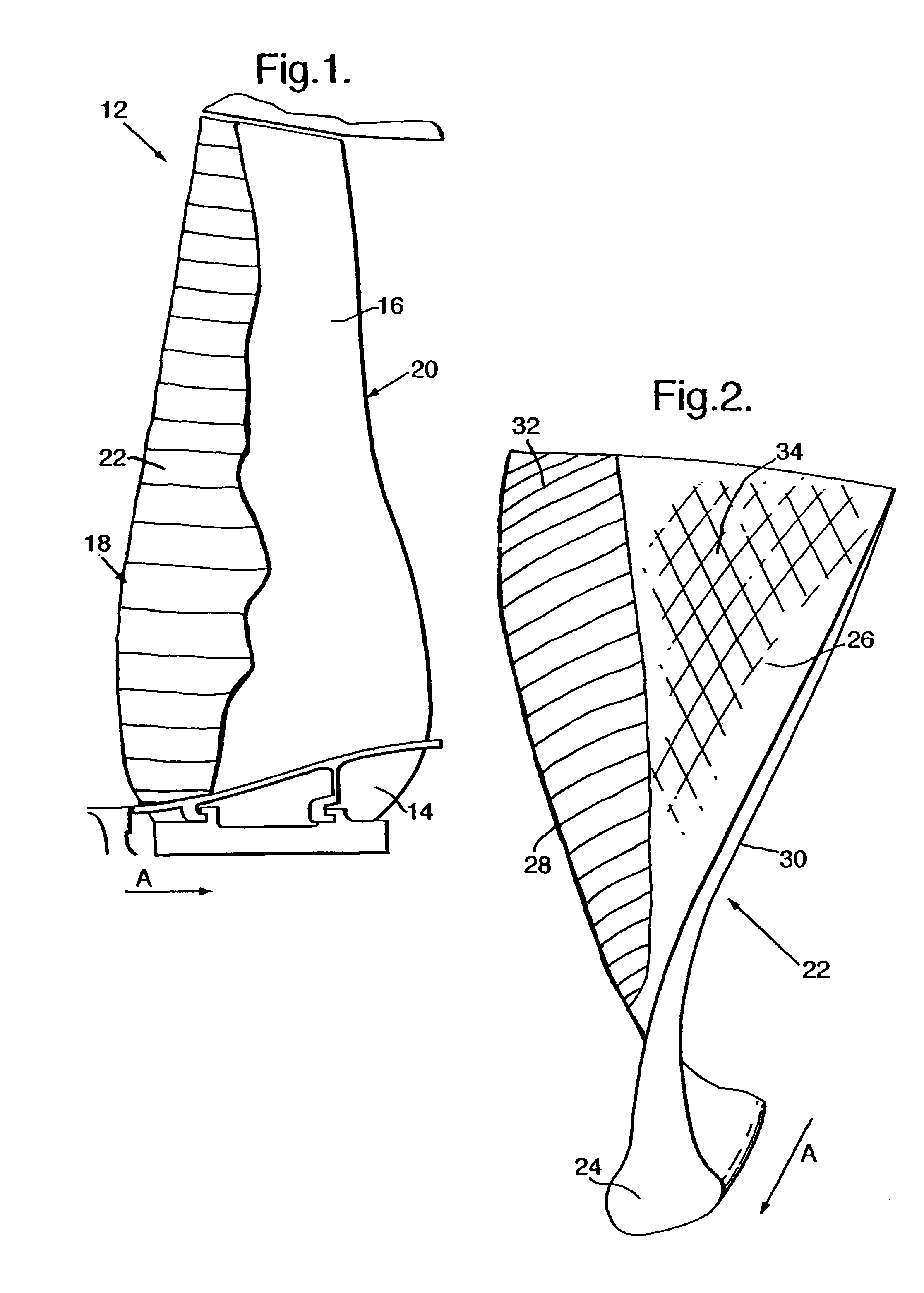
[0024]FIG. 4 shows part of the aerofoil surface of a composite fan blade 22, as shown in FIG. 2. In this third embodiment of the invention, The weave 54 of the outer wrap of the blade 22 includes fibres 56 of a shape memory alloy (SMA).

[0025]A phenomenon known as pseudoelasticity occurs in SMAs when the alloy is completely composed of austenite (i.e. when the temperature is greater than Af, the temperature at which the austenite phase finishes forming). As an increasing force is applied to the SMA, the austenite becomes transformed into martensite. This transformation occurs without any change in the temperature of the alloy. Once the loading is decreased, the martensite begins to transform back to austenite (because the temperature of the alloy is still above Af) and the SMA returns to its original shape. This reverse transformation releases energy as heat (the energy that was originally put into the alloy by applying a force to it). In the embodiment of FIG. 4, vibrations in the b...


PUM

PropertyMeasurementUnit
Glass transition temperatureaaaaaaaaaa
Viscoelasticityaaaaaaaaaa

Abstract

Aerofoils (22) of a gas turbine engine are provided with a coating (34) or filler (44) of viscoelastic material. As ice accretes on the aerofoils (22) during operation, the resulting aerodynamic stability imbalance induces vibration in the aerofoils (22). The viscoelastic material (34, 44) damps this vibration, and in so doing generates heat, which melts the ice away from the aerofoils (22). Heat-conducting members conduct the heat to regions of the component in which ice accretion is to be prevented. Alternative embodiments are described in which the pseudoelastic behaviour of a shape memory alloy (56), or eddy currents arising from the rotor blades' rotation in an axisymmetric magnetic field, are used as sources of heat.

Description

CROSS-REFERENCE TO RELATED APPLICATIONS[0001]This claims priority to United Kingdom Patent Application No. 0609704.2, filed 17 May 2006.FIELD OF THE INVENTION[0002]This invention relates to gas turbine engines, and more particularly to those components that are prone to ice accretion in use.BACKGROUND OF THE INVENTION[0003]Icing of the engine commonly occurs during flight through clouds containing supercooled water droplets or during ground operation in freezing fog. Ice can accumulate on the intake leading edge, the fan spinner, the fan blades and even further into the engine. Ice tends to form first on the leading edges of components, altering the airflow, reducing lift, increasing drag and adding weight. Relatively small amounts of ice can have a disproportionate effect on aircraft performance. Additionally, damage may result from ice breaking away and being ingested into the engine or hitting the acoustic material lining the intake duct.[0004]Anti-icing operations are conducted ...

Claims


Application Information

Patent Timeline
IPC IPC(8): F01D5/16F01D5/18
CPCF01D5/26F01D25/02F04D29/023F04D29/324Y02T50/672Y02T50/673F05D2300/43F05D2230/90F05D2300/611F05D2300/507F05D2300/505Y02T50/60B64D15/16F02C7/047F04D29/38
Inventor READ, SIMONMCMILLAN, ALISON JRAVEY, ERIC
Owner ROLLS ROYCE PLC
Why Eureka
Try Eureka