
Prosthetic implant and assembly method

a technology of prosthetic implants and assembly methods, applied in the field of prosthetic implants, can solve problems such as interfering fit at certain juxtaposed surfaces, and achieve the effects of reducing diametric dimensions, facilitating the final mating of subassembly, and small tolerances

Active Publication Date: 2011-10-11
ASCENSION ORTHOPEDICS
View PDF23 Cites 13 Cited by
  • Summary
  • Abstract
  • Description
  • Claims
  • Application Information

AI Technical Summary

Benefits of technology

"The invention is a prosthetic implant that uses a one-piece polymeric insert to join a metal stem and a head made of crystalline material. The polymeric insert is designed to fit snugly into the head and can accommodate small tolerances in the interior of the head. The insert has an interior cavity that can deform elastically to enter the head and then return to its original shape. The design also allows for a strong connection between the insert and the stem, preventing any disassembly of the assembly. The technical effects of the invention include improved stability and secure fitting of the implant components."

Problems solved by technology

Depending upon the ultimate arrangement desired, the proportioning may be such that the insert, upon return to its original physical configuration, may result in an interference fit at certain juxtaposed surfaces.

Method used


Image

  • Prosthetic implant and assembly method
  • Prosthetic implant and assembly method
  • Prosthetic implant and assembly method

Examples


Embodiment Construction

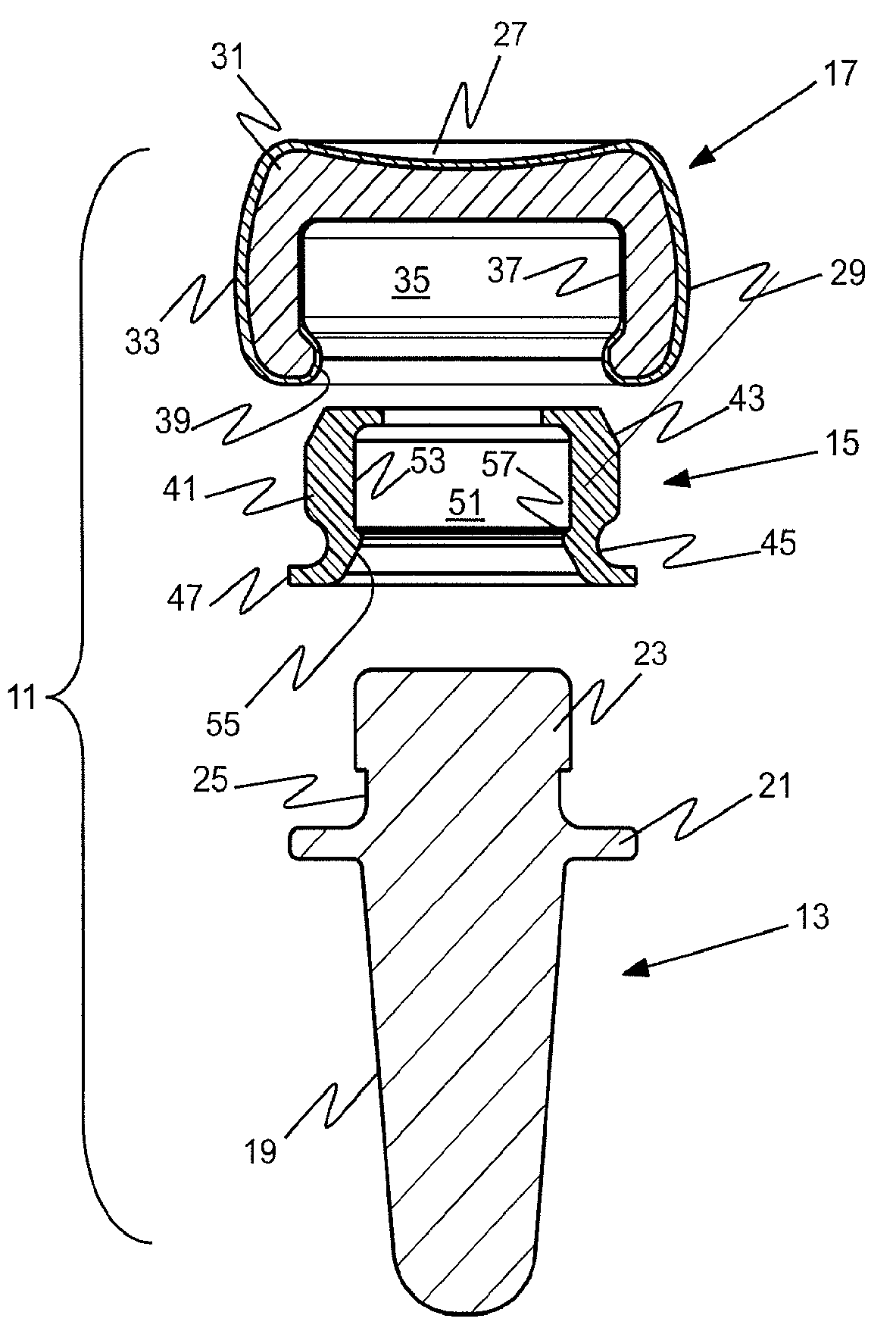
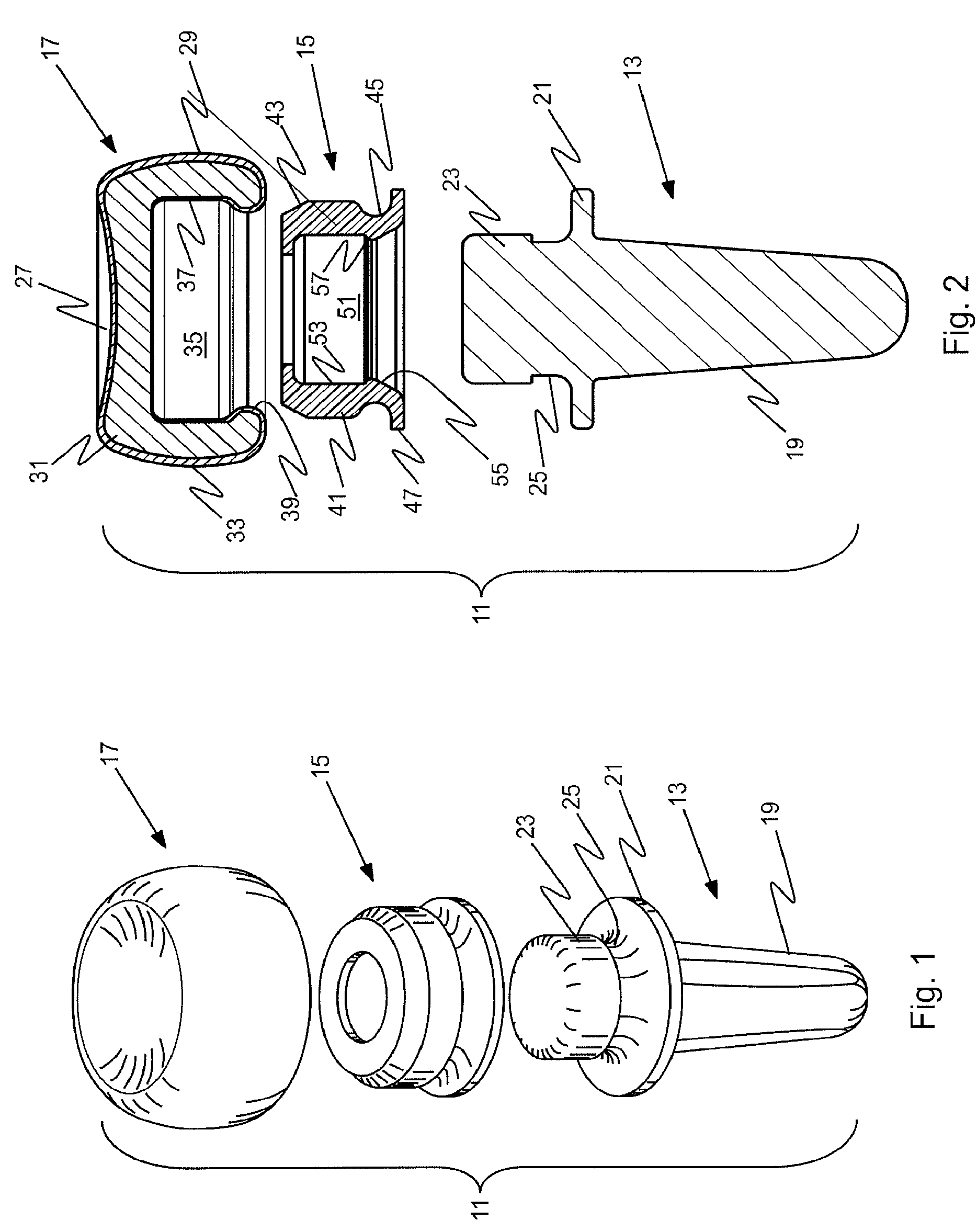
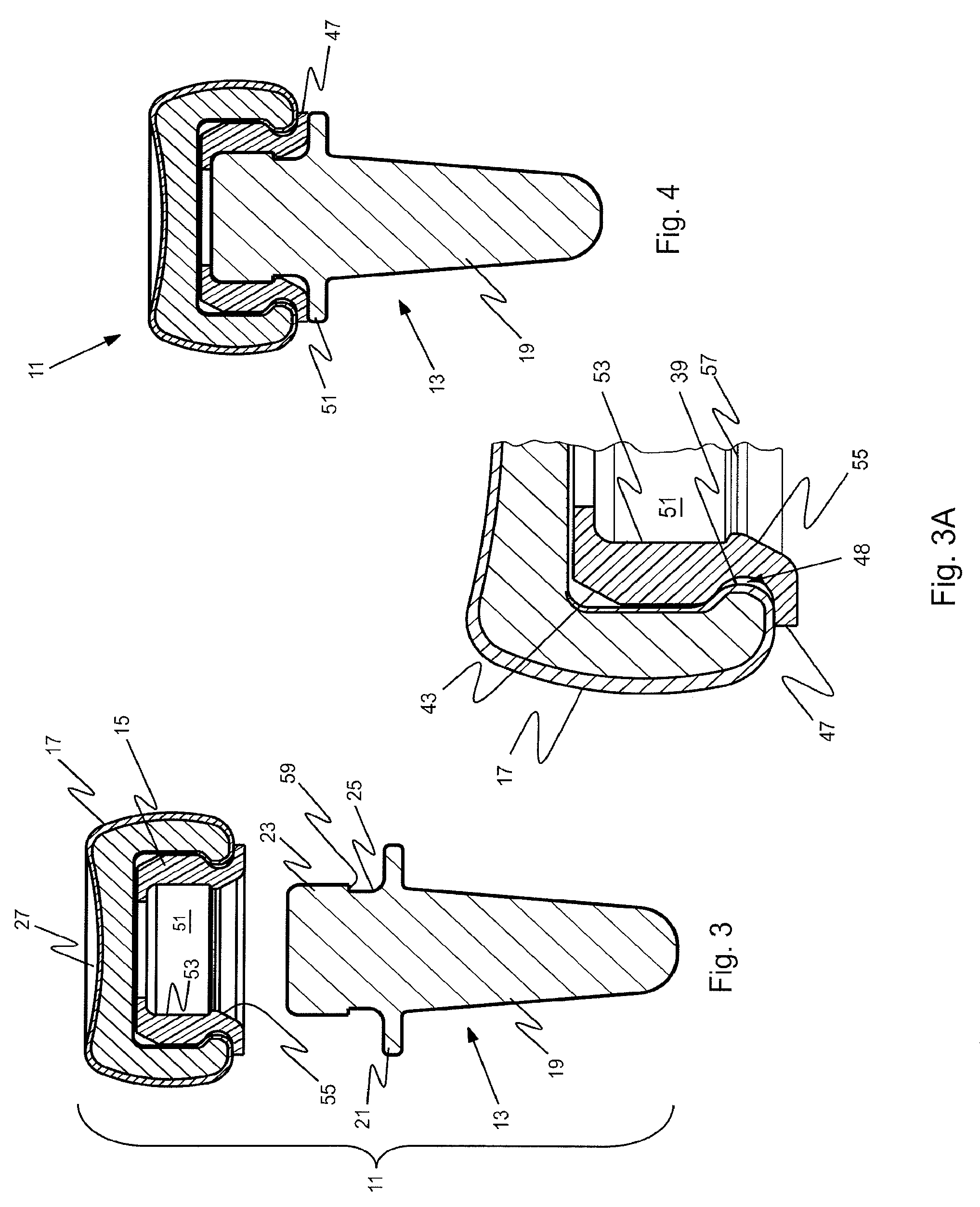
[0020]Illustrated in FIGS. 1 through 4 is a prosthetic implant 11 designed to replace the proximal end portion of the radius. The implant 11 consists of three components: a metal alloy stem element 13, a plastic insert 15 and a head 17 of a brittle, crystalline, nonmetallic material, preferably a pyrocarbon-coated graphite substrate. When it is necessary to replace the proximal head of the radius for whatever reason, the implant provides an axisymmetric prosthesis similar to that shown in U.S. Pat. No. 6,217,616, entitled Elbow Prosthesis. By brittle is meant a crystalline material that fractures or fails instead of undergoing permanent deformation; such materials, although strong in compression, are inherently weak in tension.

[0021]The stem element 13 includes a stem portion 19 that is proportioned to be received in the medullary cavity of the resected radius. The stem portion may have any suitable cross-section, e.g. conical, cylindrical, polygonal or splined; it is designed to re...


PUM

PropertyMeasurementUnit
thickaaaaaaaaaa
thickaaaaaaaaaa
thickaaaaaaaaaa

Abstract

An orthopedic prosthetic implant comprises a metal alloy stem element (13, 63, 113), which has one end portion (19, 69, 119) constructed to reside in the medullary cavity of a bone and an integral connector (23, 73, 123) at the opposite end to which crystalline brittle head (17, 67, 117), preferably made of pyrocarbon-coated graphite, is joined. The head interfaces with human bone, and its effective joinder to the stem element is achieved through a polymeric insert (15, 65, 115) of proportional shape and design which has selected elastic properties. The design and material of the polymeric insert allow it to be securely received within an interior cavity (35, 77, 131) of the pyrocarbon-coated graphite head and mated to the stem connector in an either rigidly or bi-polar arrangement. The method of joinder allows the construction of composite implants that utilize the most desirable properties of metallic and brittle crystalline materials.

Description

[0001]This application is a continuation of International Application No. PCT / US07 / 64594, filed 22 Mar. 2007, which claims priority from U.S. Provisional Application Ser. No. 60 / 743,661, filed Mar. 22, 2006, the disclosures of both of which are incorporated herein by reference.[0002]This invention relates to prosthetic bone implants, and more particularly to a prosthetic bone implant to be used at a biological joint, and to methods for making such implants. Still more particularly, the invention relates to a prosthetic implant wherein a metal stem is joined to a head made of brittle crystalline material and to such assembly methods.BACKGROUND OF THE INVENTION[0003]The field of prosthetic implants to treat conditions of fracture, arthritis and other such conditions has grown greatly in the past 2-3 decades, and much work continues in these areas. Pyrocarbon-coated graphite materials have proved to be extremely wear-resistant and biocompatible, and they have become the materials of ch...

Claims


Application Information

Patent Timeline
Patent Type & Authority Patents(United States)
IPC IPC(8): A61F2/32
CPCA61F2/3804A61F2/30767A61F2002/30113A61F2002/30324A61F2002/30878Y10T29/49826A61F2230/0006A61F2250/0036A61F2310/00173A61F2310/00574A61F2002/3827
Inventor VANDER MEULEN, STEVEKLAWITTER, JEROME J.
Owner ASCENSION ORTHOPEDICS
Learn More