Mid-plane mounted optical communications system and method for providing high-density mid-plane mounting of parallel optical communications modules

a technology of optical communication system and parallel optical communication module, which is applied in the direction of optical elements, coupling device connections, instruments, etc., can solve the problems of inability to achieve very large bandwidth increases of such arrays, racks and cabling needed to accommodate transceiver modules, and inability to achieve large bandwidth increases in many cases

Inactive Publication Date: 2011-10-11
AVAGO TECH INT SALES PTE LTD
View PDF8 Cites 82 Cited by
  • Summary
  • Abstract
  • Description
  • Claims
  • Application Information

AI Technical Summary

Problems solved by technology

One of the problems associated with such an array is that because the MTP connectors are edge-mounted in receptacles formed in the front panel of the optical communications system, there are limitations on the ability of such an array to achieve very large increases in bandwidth.
For example, in order to obtain an optical communications system that has the ability to simultaneously transmit and receive one terabit of data per second (Tb / s), the racks and cabling needed to accommodate the transceiver modules would consume so much space that the solution would be impractical in many cases.
In addition, an array of this type would present heat dissipation problems, and in most cases, would be prohibitively expensive.
The racks needed to accommodate this many boxes and the cables needed to interconnect the boxes to the router ICs consume a large amount of space and generate a large amount of heat.
In addition, the Snap 12 transmit and receive modules are relatively tall (approximately 15 mm in height), which often results in the occurrence of relatively large impedance disturbances in the modules.
These impedance disturbances reduce signal integrity and therefore limit the bandwidth efficiency of the system.
Also, each Snap 12 box is sold as a stand-alone part that is relatively expensive.
Consequently, a system that is constructed of multiple boxes in order to achieve an increased bandwidth is generally very expensive.
One of the problems associated with the existing or proposed mid-plane mounting solutions is that there are limitations on the mounting density of the modules on the motherboard PCB.
Consequently, the number of modules that can be mounted on the motherboard is limited by the additional space needed between adjacent modules to accommodate the cables.
In addition, with known edge-mounting and mid-plane mounting configurations, the electrical conductors that electrically connect the circuitry of the modules to their respective hub ICs on the motherboard PCB have to be relatively long.
Because these modules often operate at the limits of the latest high-speed electronics, the long conductor lengths tend to create signal integrity problems.

Method used


Image

  • Mid-plane mounted optical communications system and method for providing high-density mid-plane mounting of parallel optical communications modules
  • Mid-plane mounted optical communications system and method for providing high-density mid-plane mounting of parallel optical communications modules
  • Mid-plane mounted optical communications system and method for providing high-density mid-plane mounting of parallel optical communications modules

Examples


Embodiment Construction

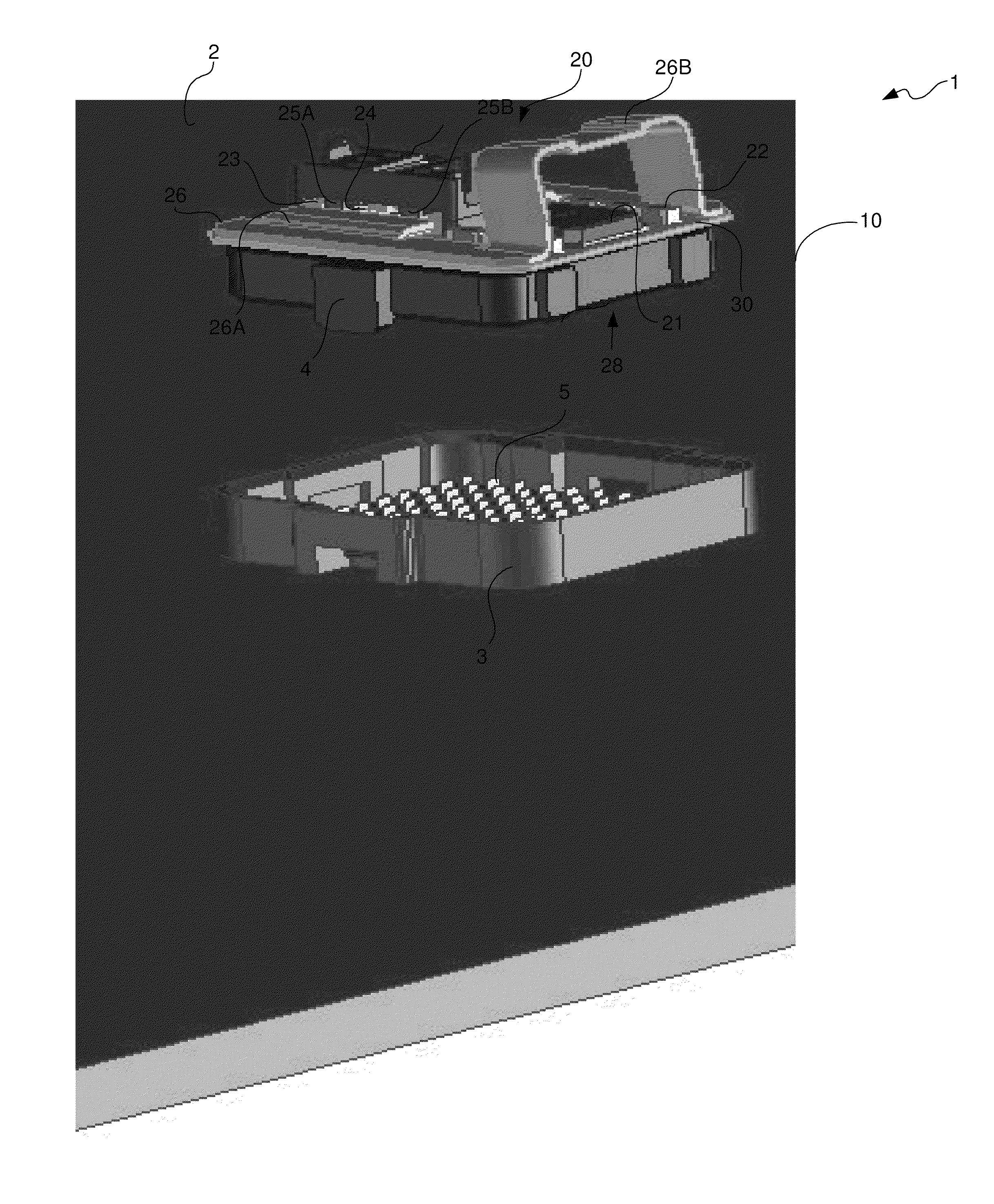
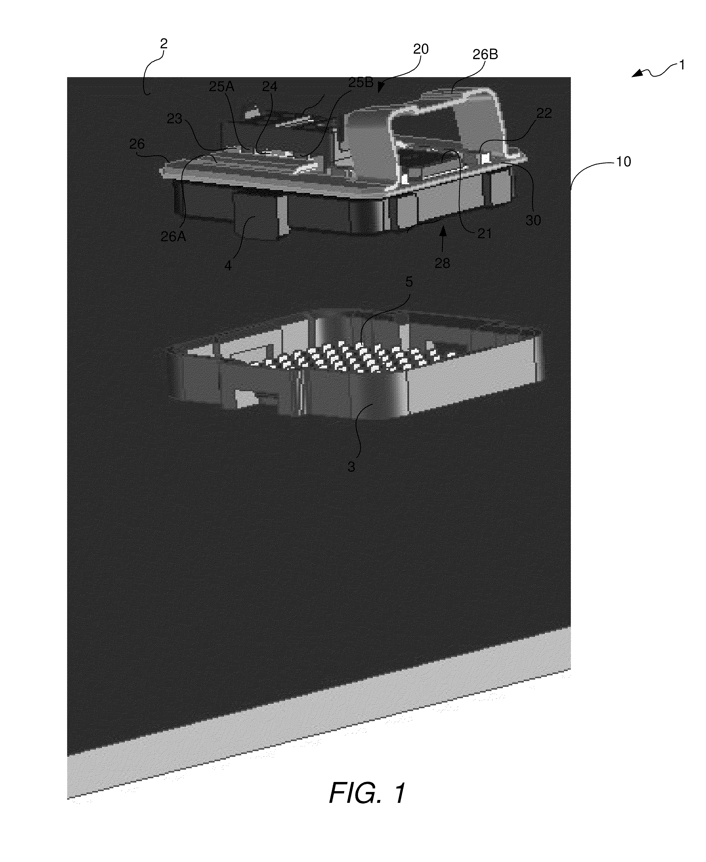
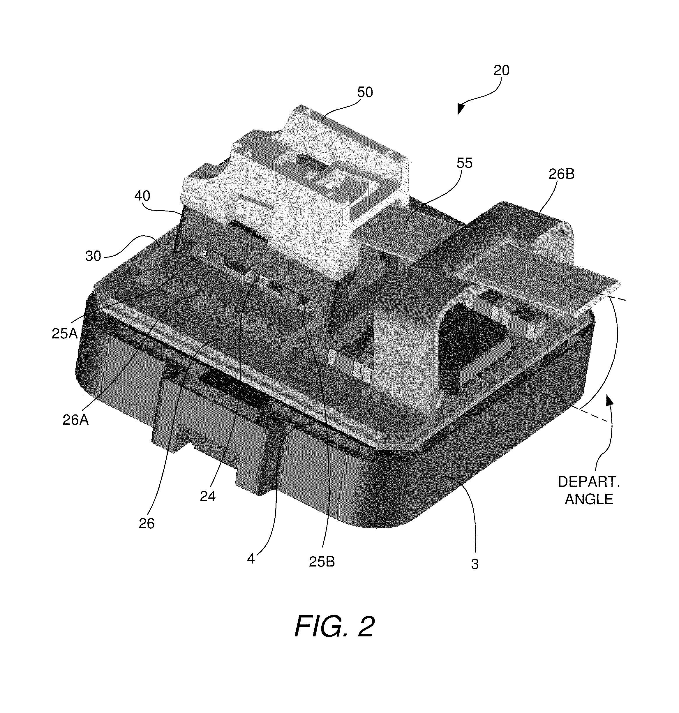
[0029]In accordance with the invention, an optical communications system is provided comprising multiple parallel optical communications modules that are mid-plane mounted on a PCB motherboard of the type that is sometimes referred to as a card or a blade. Each module is connected to an optical fiber ribbon cable. The modules are configured to have very low profiles and / or to provide an angular coupling of the ribbon cable to the module. In both cases, the module configurations enable the modules to be mounted on the motherboard PCB with very little or no space between adjacent modules because the need for space for the ribbon cables to exit the modules is eliminated or lessened. This feature allows the module mounting density on the motherboard PCB to be very high and allows the modules to be mounted closer to their respective hub ICs. The higher mounting density increases the overall bandwidth of the system, whereas mounting the modules closer to their respective ICs allows the le...


PUM


Abstract

An optical communications system and method are provided in which multiple parallel optical communications modules are mid-plane mounted on a PCB motherboard. Each module is connected to an optical fiber ribbon cable. The modules are configured to have very low profiles and / or to provide an angular coupling of the ribbon cable to the module. In both cases, the module configurations obviate the need to leave a significant amount of space between a module and the one behind it for the purpose of providing room for the ribbon cable to exit the module without the cable being bent beyond its minimum bend radius. This feature allows the module mounting density on the motherboard PCB to be very high and allows the modules to be mounted closer to their respective hub ICs, which increases mounting density and allows the modules to be mounted closer to their respective hub ICs.

Description

TECHNICAL FIELD OF THE INVENTION[0001]The invention relates to optical communications systems. More particularly, the invention relates to an optical communications system and method for high-density, mid-plane mounting of multiple parallel optical communications modules.BACKGROUND OF THE INVENTION[0002]A parallel optical communications module is a module having multiple transmit (TX) channels, multiple receive (RX) channels, or both. A parallel optical transceiver module is an optical communications module that has multiple TX channels and multiple RX channels in the TX and RX portions, respectively, of the transceiver. The TX portion comprises components for transmitting data in the form of modulated optical signals over multiple optical waveguides, which are typically optical fibers. The TX portion includes a laser driver circuit and a plurality of laser diodes. The laser driver circuit outputs electrical signals to the laser diodes to modulate them. When the laser diodes are mod...

Claims


Application Information

Patent Timeline
Patent Type & Authority Patents(United States)
IPC IPC(8): G02B6/12G02B6/36G02B6/00
CPCG02B6/4201G02B6/4206G02B6/43G02B6/4246G02B6/4214
Inventor MCCOLLOCH, LAURENCE R.
Owner AVAGO TECH INT SALES PTE LTD
Why Eureka
Try Eureka