
Method for making a part of composite material with ceramic matrix and resulting part

a composite material and ceramic matrix technology, applied in the direction of magnetic recording, chemical vapor deposition coating, coating, etc., can solve the problems of material fragility, lack of fiber-matrix bonding to the detriment of mechanical force resistance, and the technique cannot be implemented in the same manner with a liquid composition, so as to achieve less oxidation resistance, easy to work, and good deformation.

Active Publication Date: 2011-10-18
SAFRAN CERAMICS SA
View PDF12 Cites 10 Cited by
  • Summary
  • Abstract
  • Description
  • Claims
  • Application Information

AI Technical Summary

Benefits of technology

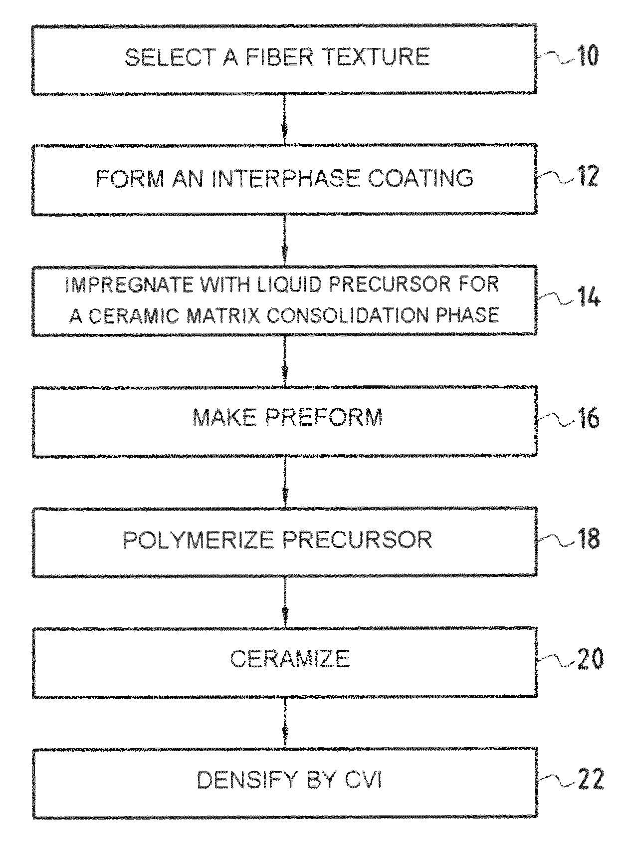
The invention proposes a method for making a composite material part by using a liquid technique to form an interphase coating on the fibers of a fiber reinforcement, followed by consolidation with a ceramic matrix. The interphase coating consists of an inner layer in contact with the fibers to provide embrittlement relief and an outer layer for bonding with the ceramic matrix. The consolidation is done by impregnating the fiber preform with a liquid composition and using a chemical vapor infiltration process to transform the precursor into the ceramic material of the matrix. The resulting composite material part has good mechanical properties and can be used in high-performance applications.

Problems solved by technology

Although consolidating a fiber preform by a liquid technique is itself known, when forming a consolidating phase out of carbon, the Applicant has found that that technique cannot be implemented in the same manner with a liquid composition that is a precursor for a ceramic.
For a preform made of carbon fibers (or coated in carbon), there is no adhesion between the ceramic precursor and the fibers, and that leads to lack of fiber-matrix bonding to the detriment of the ability to withstand mechanical forces.
In contrast, with a ceramic fiber preform, adhesion is very strong and leads to fiber-matrix bonding that is too strong, thus making the material fragile.

Method used


Image

  • Method for making a part of composite material with ceramic matrix and resulting part
  • Method for making a part of composite material with ceramic matrix and resulting part

Examples


example 1

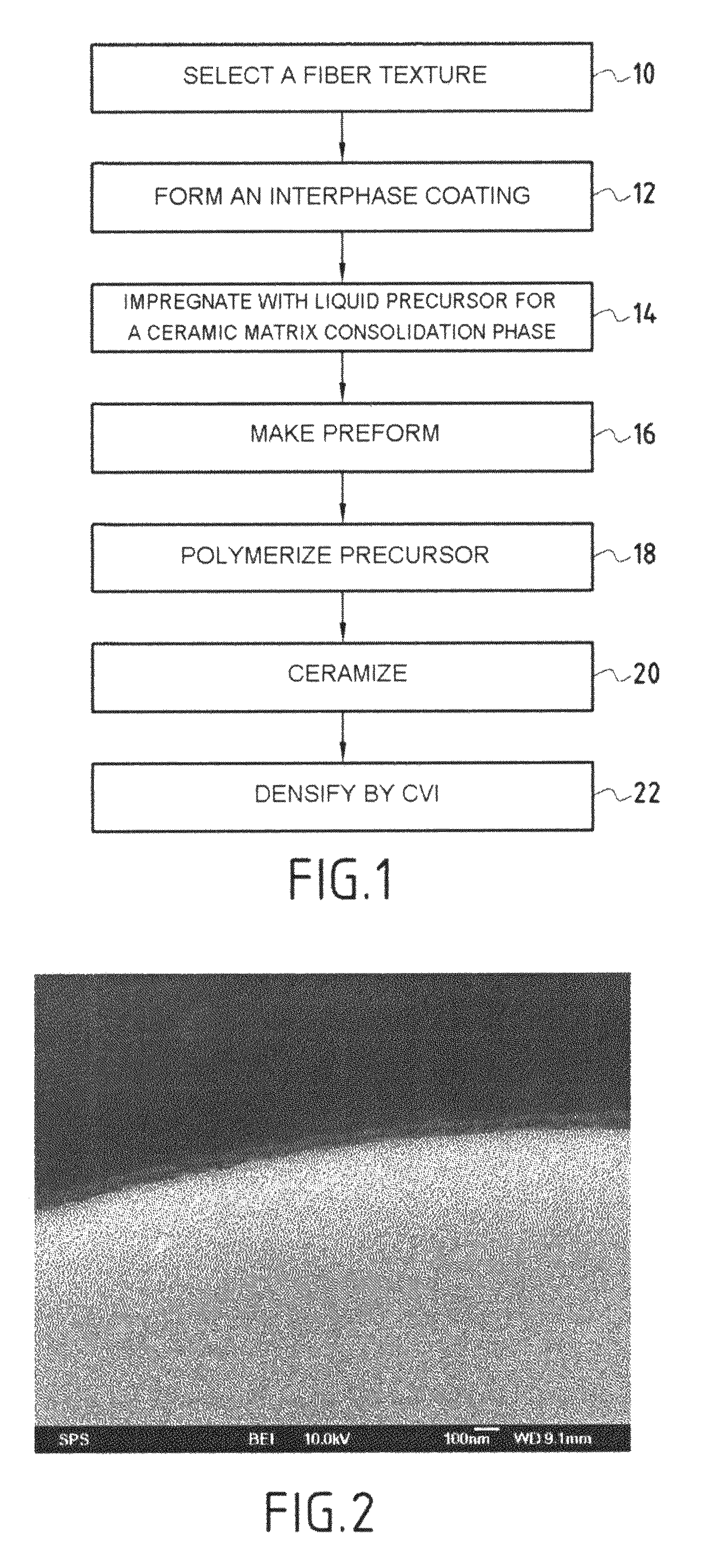
[0059]A fiber texture was used constituted by a multilayer woven fabric (30) of fiber yarns made essentially of SiC as supplied under the reference “Hi-Nicalon” by the Japanese supplier Nippon Carbon, the fibers being united by a polyvinyl alcohol (PVA) reaming filament. A BC / SiC interphase coating (inner layer of BC and outer layer of SiC) was formed on the fibers by a CVI process. The thickness of the interphase coating was about 50 nm, the BC and SiC layers being of substantially the same thickness. The microphotograph of FIG. 2 shows the interphase coating formed on an SiC fiber.

[0060]The fiber texture provided with the interphase coating was impregnated by being passed through a bath containing a polycarbosilazane resin, a precursor of SiC, in solution in xylene, and then drying, so as to leave on the fibers a quantity of resin constituting about 40% by weight relative to the weight of the texture provided with the interphase coating.

[0061]A ply of impregnated fiber texture was...


PUM

PropertyMeasurementUnit
thicknessaaaaaaaaaa
temperaturesaaaaaaaaaa
thicknessaaaaaaaaaa

Abstract

An interphase coating is formed by chemical vapor infiltration (CVI) on the fibers constituting a fiber preform, the interphase coating comprising at least an inner layer in contact with the fibers for embrittlement relief to the composite material, and an outer layer for bonding with the ceramic matrix. The fiber preform is then kept in its shape by the fibers provided with the interphase coating and is consolidated by being impregnated with a liquid composition containing a ceramic precursor, and by transforming the precursor into a ceramic matrix consolidation phase. The consolidated preform is then densified by an additional ceramic matrix phase. No support tooling is needed for forming the interphase coating by CVI or for densification after consolidation using the liquid technique.

Description

[0001]This application is a §371 national phase filing of PCT / FR2006 / 050157 filed Feb. 22, 2006, and claims priority to French application No. 05 01826 filed Feb. 23, 2005.BACKGROUND OF THE INVENTION[0002]The invention relates to fabricating parts out of ceramic matrix composite material (CMC material).[0003]CMC materials are generally used for parts that need to present good mechanical behavior up to high temperatures, typically 1200° C. and even above, in an oxidizing environment.[0004]Applications for CMC materials are to be found in the aviation and space fields, for example for structural parts that are exposed to a stream of hot gas in an aero-engine.[0005]CMC materials are formed on a fiber reinforcing substrate that is densified with a ceramic matrix. The substrate may be made of carbon fibers or of ceramic fibers, such as refractory oxide or nitride or carbide fibers (typically silicon carbide SiC).[0006]A method of making CMC material is described in document U.S. Pat. No....

Claims


Application Information

Patent Timeline
Patent Type & Authority Patents(United States)
IPC IPC(8): C23C16/00
CPCC04B35/565C04B35/6286C04B35/62863C04B35/62868C04B35/62873C04B35/62884C04B35/62894C04B35/62897C04B35/806C04B35/571Y10T428/265C04B2235/465C04B2235/5244C04B2235/80C04B2235/96C04B35/80
Inventor PHILIPPE, ERICBERTRAND, SEBASTIENBOUILLON, ERICCAILLAUD, ALAINICHARD, JEAN-CHRISTOPHEBAGAT, ROBERT
Owner SAFRAN CERAMICS SA
Learn More