Apparatus for and method of processing substrate

a substrate and processing apparatus technology, applied in the direction of liquid processing circulation, instruments, photosensitive materials, etc., can solve the problems of not being able to quickly remove foreign substances contained within the processing bath, not being able to efficiently drain the used processing liquid the background art substrate processing apparatus b>100/b> is not able to quickly remove foreign substances from the processing bath, etc., to achieve the effect of suppressing the agitation of the processing liquid

Active Publication Date: 2011-10-25
DAINIPPON SCREEN MTG CO LTD
View PDF16 Cites 8 Cited by
  • Summary
  • Abstract
  • Description
  • Claims
  • Application Information

AI Technical Summary

Benefits of technology

[0012]The processing liquid discharged from the first discharge part impinges upon the side wall or the bottom wall to diffuse, thereby moving toward the top portion of the processing bath in the form of low-speed uniform liquid flows. Thus, a metal component and foreign substances generated in the processing bath float up toward the top portion of the processing bath without being agitated within the processing bath, and are rapidly drained to the outside of the processing bath together with the processing liquid. Further, there is no need to complicate the structure of the first discharge part itself. This suppresses the manufacturing costs of the substrate processing apparatus.
[0020]The recessed portions are easily formed in the respective side walls of the processing bath. Further, the direction in which the processing liquid moves is easily determined by the inclination of tapered surfaces defining the groove of the V-shaped cross-sectional configuration.
[0026]When it is desired to improve the uniformity of the processing with the processing liquid, the second discharge part is used to form relatively high-speed liquid flows within the processing bath, thereby making the concentration of the processing liquid within the processing bath uniform. When it is desired to efficiently replace the processing liquid within the processing bath with another processing liquid, the first discharge part is used to form relatively low-speed liquid flows within the processing bath, thereby accomplishing the efficient drainage of the processing liquid from the processing bath.
[0036]While the etchant component remains in certain amounts within the processing bath, the second discharge part discharges the processing liquid to make the concentration of the etchant component uniform. After the etchant component is drained in certain amounts out of the processing bath, the first discharge part discharges the processing liquid to efficiently drain the remaining etchant component from the processing bath.
[0042]It is therefore an object of the present invention to provide an apparatus for and a method of processing a substrate which are capable of suppressing the agitation of a processing liquid within a processing bath to drain foreign substances such as particles out of the processing bath efficiently.

Problems solved by technology

Such a conventional form of discharge, however, is intended to agitate the processing liquid all over the inside of the processing bath 110, and is not capable of efficiently draining a used processing liquid from the processing bath 110 to replace the used processing liquid with a new processing liquid.
Thus, the background art substrate processing apparatus 100 is not capable of rapidly remove the foreign substances contained within the processing bath 110 from the processing bath 110.
Such foreign substances are deposited onto the surfaces of the substrates W being processed to give rise to apprehensions about the contamination of the substrates W and about the processing failures of the substrates W. In particular, when an acid chemical liquid is used as the processing liquid or when substrates W having hydrophobic surfaces are used, the foreign substances such as particles are prone to adhere to the surfaces of the substrates W to make the above-mentioned problem more serious.
The background art substrate processing apparatus is not capable of satisfying both the requirement for improvements in processing uniformity of the processing liquid and the requirement for efficient replacement of the processing liquid stored within the processing bath with another processing liquid.

Method used


Image

  • Apparatus for and method of processing substrate
  • Apparatus for and method of processing substrate
  • Apparatus for and method of processing substrate

Examples


Embodiment Construction

[0058]Preferred embodiments according to the present invention will now be described with reference to the drawings.

1. First Preferred Embodiment

[0059]

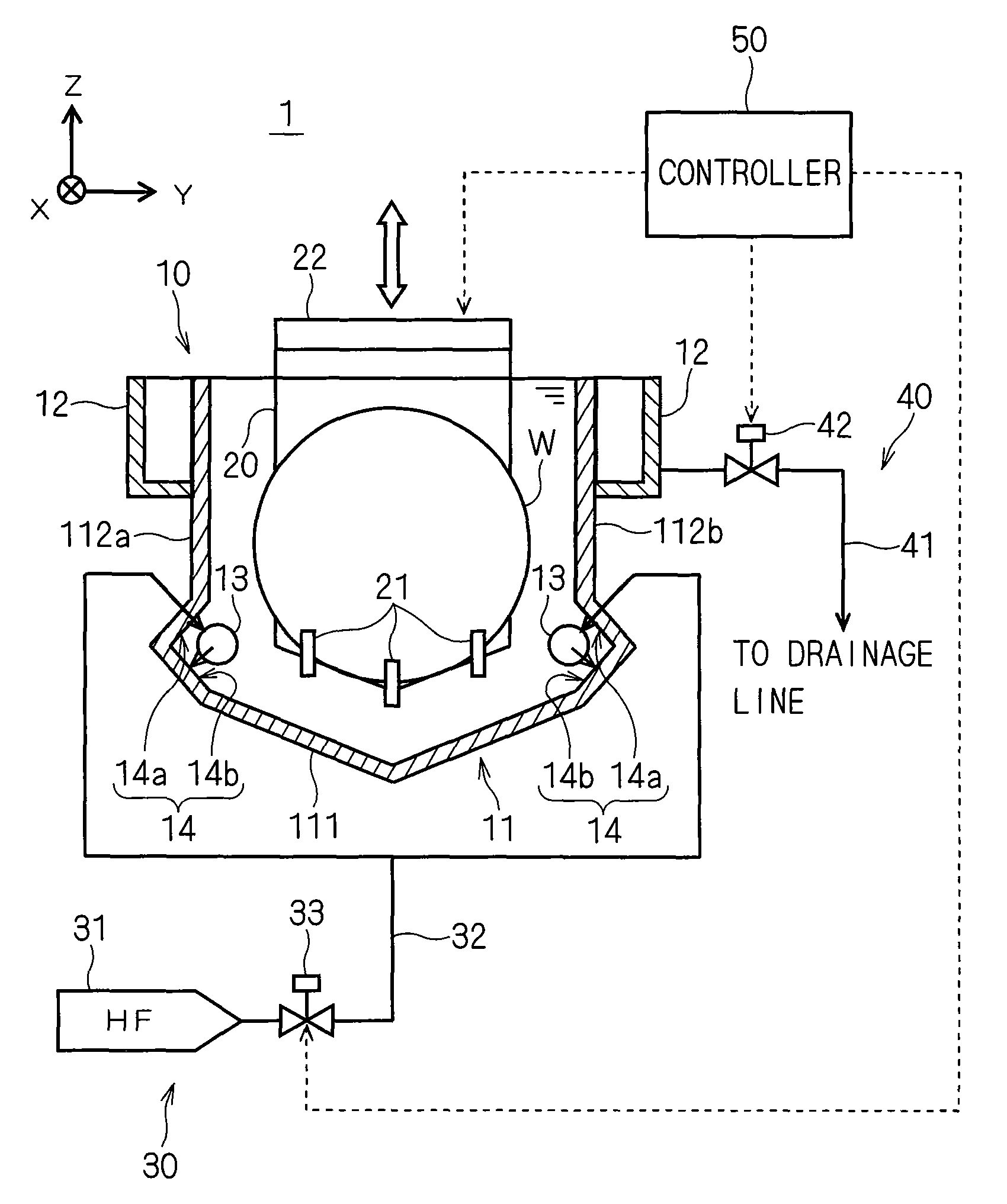
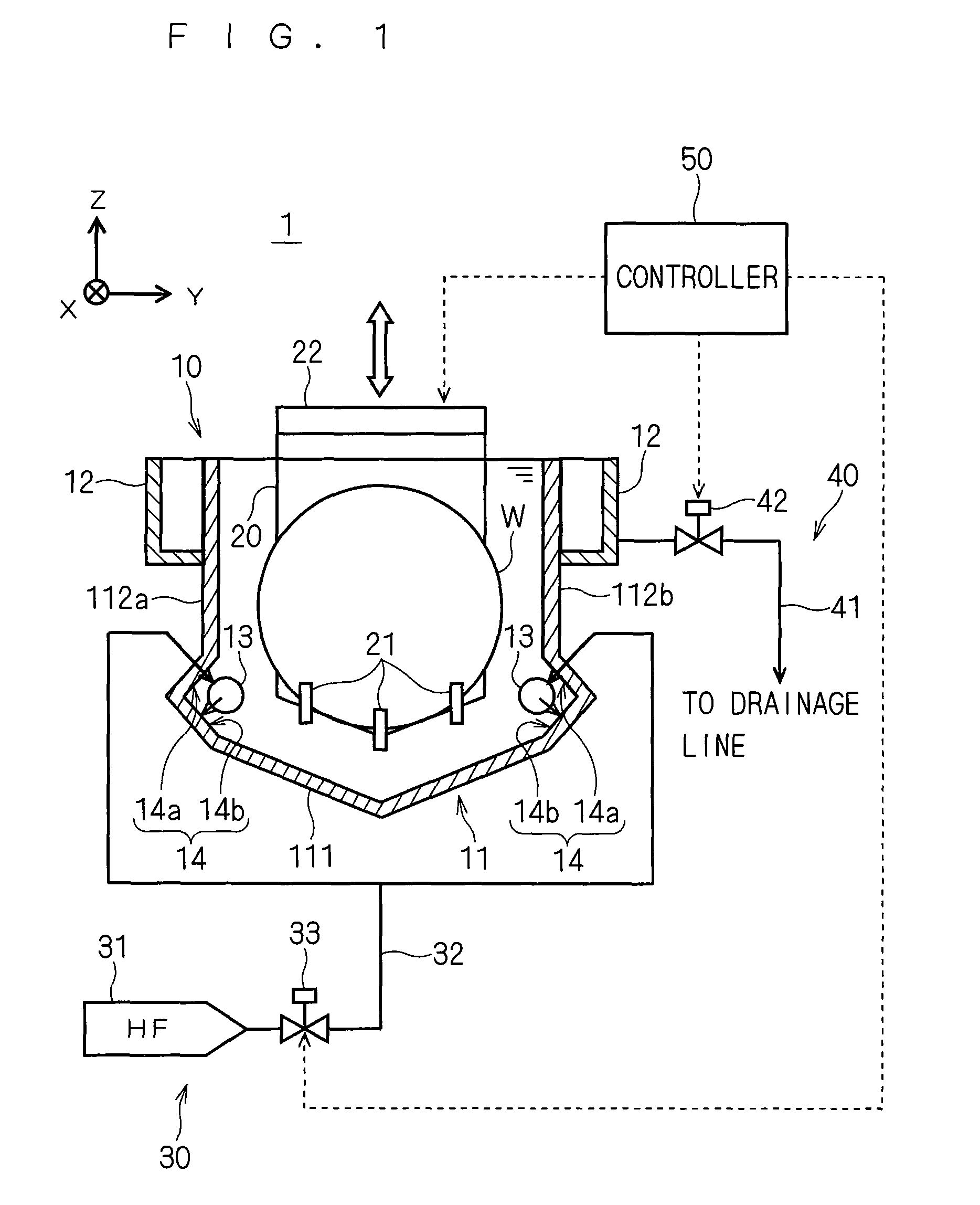
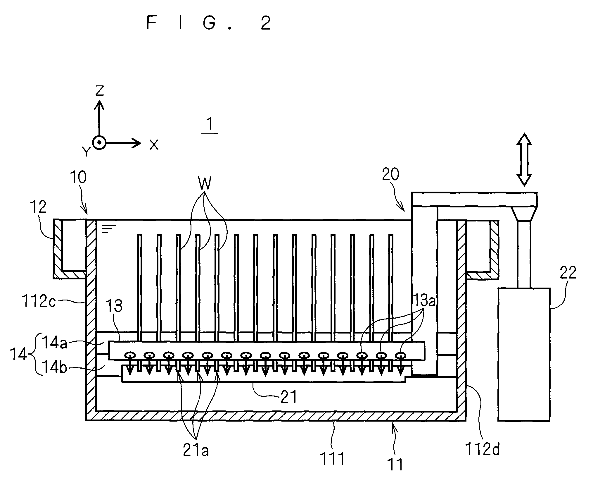
[0060]FIG. 1 is a vertical sectional view of a substrate processing apparatus 1 taken along a plane parallel to the main surfaces of substrates W according to a first preferred embodiment of the present invention. The construction of a control system and liquid supply and drainage systems included in the substrate processing apparatus 1 is also shown in FIG. 1. FIG. 2 is a vertical sectional view of the substrate processing apparatus 1 taken along a plane perpendicular to the main surfaces of the substrates W. A common XYZ rectangular coordinate system is additionally shown in FIGS. 1 and 2 for purposes of clarifying the positional relationship between components in the substrate processing apparatus 1.

[0061]This substrate processing apparatus 1 is an apparatus which stores a hydrofluoric acid (HF) solution within a processing bath 10...


PUM

PropertyMeasurementUnit
diameteraaaaaaaaaa
diameteraaaaaaaaaa
diameteraaaaaaaaaa

Abstract

A substrate processing apparatus discharges a hydrofluoric acid solution from discharge nozzles toward grooves formed in side walls of an inner bath. The hydrofluoric acid solution discharged from the discharge nozzles impinges upon the grooves to diffuse, thereby moving toward a top portion of the inner bath in the form of low-speed uniform liquid flows. Thus, a metal component and foreign substances generated in the inner bath float up toward the top portion of the inner bath without being agitated within the inner bath, and are rapidly drained to an outer bath together with the hydrofluoric acid solution.

Description

BACKGROUND OF THE INVENTION[0001]1. Field of the Invention[0002]The present invention relates to a substrate processing apparatus for performing a cleaning process, an etching process and other processes upon substrates such as semiconductor substrates, glass substrates for a liquid crystal display device, glass substrates for a photomask and the like by dipping the substrates in a processing liquid.[0003]2. Description of the Background Art[0004]In the process of manufacturing substrates, a substrate processing apparatus is used which processes the substrates by dipping the substrates in a processing liquid stored in a processing bath. FIG. 18 is a view showing an example of a background art substrate processing apparatus 100. As shown in FIG. 18, the background art substrate processing apparatus 100 includes a processing bath 110 for storing a processing liquid therein, and causes the processing liquid to overflow from a top portion of the processing bath 110 while discharging the...

Claims


Application Information

Patent Timeline
Patent Type & Authority Patents(United States)
IPC IPC(8): H01L21/306C23F1/00
CPCG03D3/02H01L21/67057H01L21/67086H01L21/302H01L21/304
Inventor OSAWA, ATSUSHIABIKO, YOSHITAKA
Owner DAINIPPON SCREEN MTG CO LTD
Why Eureka
Try Eureka