Variable arc gap plasma igniter

a plasma igniter and variable arc gap technology, which is applied in the direction of burner ignition devices, manufacturing tools, lighting and heating apparatus, etc., can solve the problems of small gaps being subject to short circuits, failures in other locations, and the air gap between the two electrodes being a problem, so as to increase the gap size and increase the arc gap size

Active Publication Date: 2011-10-25
PRATT & WHITNEY CANADA CORP
View PDF30 Cites 5 Cited by
  • Summary
  • Abstract
  • Description
  • Claims
  • Application Information

AI Technical Summary

Benefits of technology

[0005]In accordance with one aspect of the present invention, there is a variable arc gap plasma igniter element which comprises a first electrode and a second electrode defining a gap therebetween, adapted to generate a plasma arc extending through the gap when an electric voltage is applied across the electrodes. There are means provided for moving the second electrode relative to the first electrode during arcing, from a first position to a second position. The second position increases the gap size relative to the first position.
[0006]In accordance with another aspect of the present invention, there is a variable arc gap plasma igniter element provided for gas turbine engines, which comprises a first electrode having an end exposed to a cavity, a second electrode moveable relative to the first electrode and spaced apart therefrom to define a variable-sized gap between the end of the first electrode and an end of the second electrode, and an apparatus adapted to move at least the second electrode to thereby vary the arc size during arcing.
[0007]In accordance with a further aspect of the present invention, there is a method provided for operating a variable arc gap plasma igniter element for gas turbine engines, which comprises setting first and second electrodes of a plasma igniter element in a close relationship to define a small arc gap therebetween, applying an electric voltage across the electrodes to initiate a plasma arc across the arc gap, increasing the arc gap size, and injecting a fuel flow adjacent the plasma arc to ignite the fuel.

Problems solved by technology

The size of the air gap between the two electrodes is a problematic in igniter design.
Larger air gaps provide plasma arcs with higher energy but require higher breakdown voltages which can lead to failure in other locations such as at lead connections.
Smaller gaps are subject to short circuit if carbon accumulates in the gap.

Method used


Image

  • Variable arc gap plasma igniter
  • Variable arc gap plasma igniter
  • Variable arc gap plasma igniter

Examples


Embodiment Construction

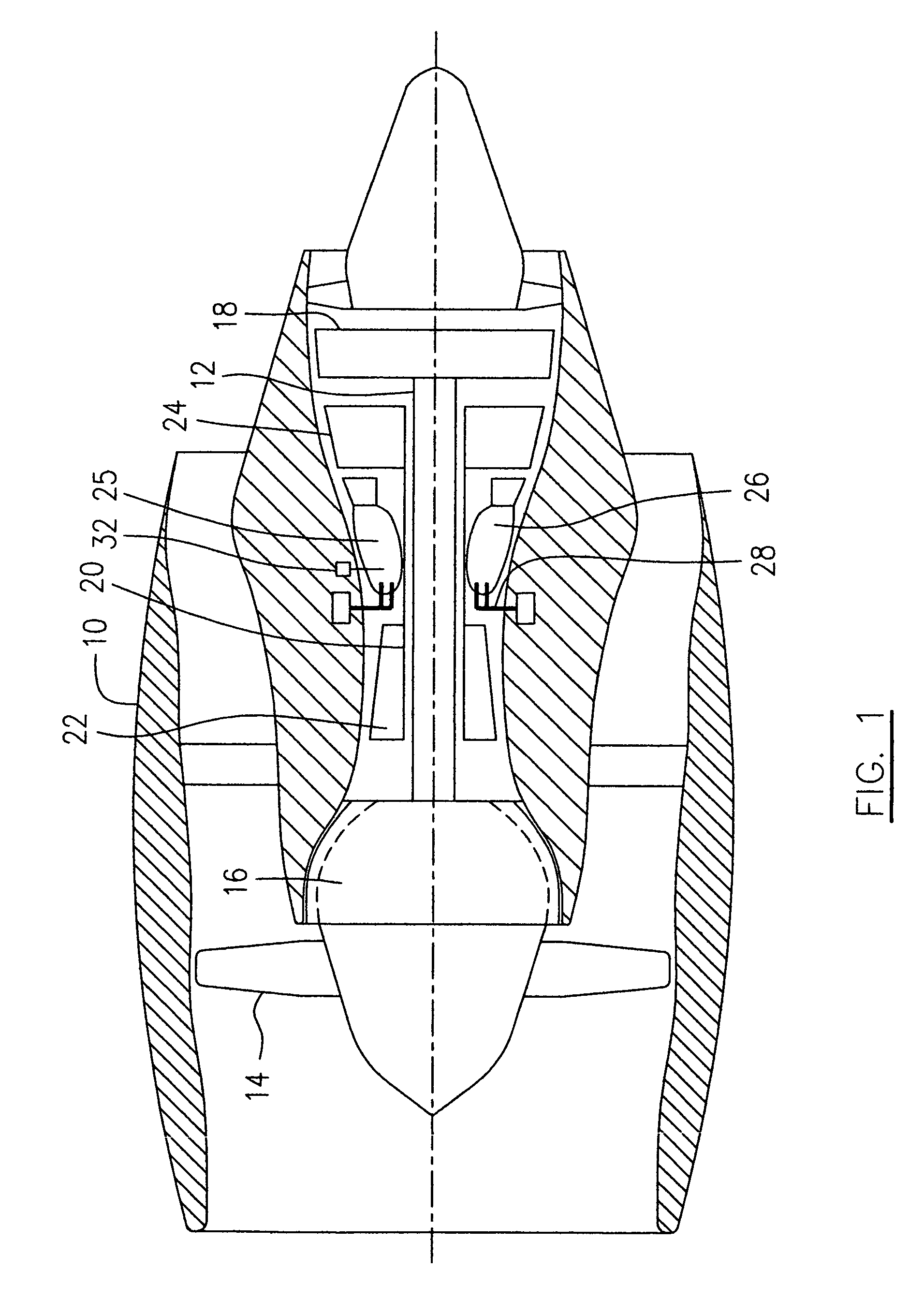
[0015]A typical application of the present invention for turbofan engines illustrated schematically in FIG. 1, incorporates an embodiment of the present invention presented as an example of the application of the present invention, and includes a housing or nacelle 10, a low pressure spool assembly seen generally at 12 which includes a fan 14, low pressure compressor 16 and low pressure turbine 18, a high pressure spool assembly seen generally at 20 which includes a high pressure compressor 22 and a high pressure turbine 24. There is provided a burner seen generally at 25 which includes an annular combustor 26 and a plurality of fuel injectors 28 for mixing liquid fuel with air and injecting the mixed fuel / air flow into the annular combustor 26 for combustion.

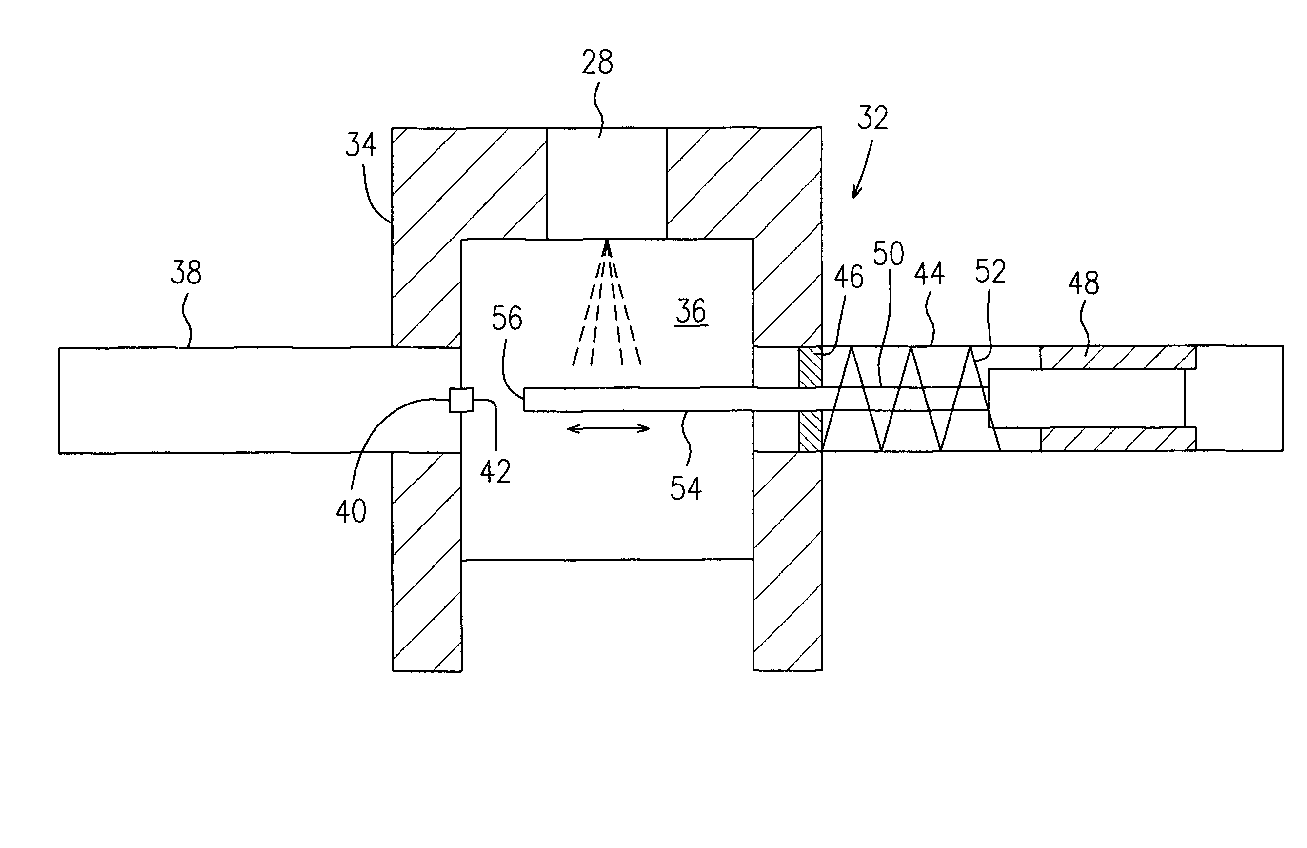
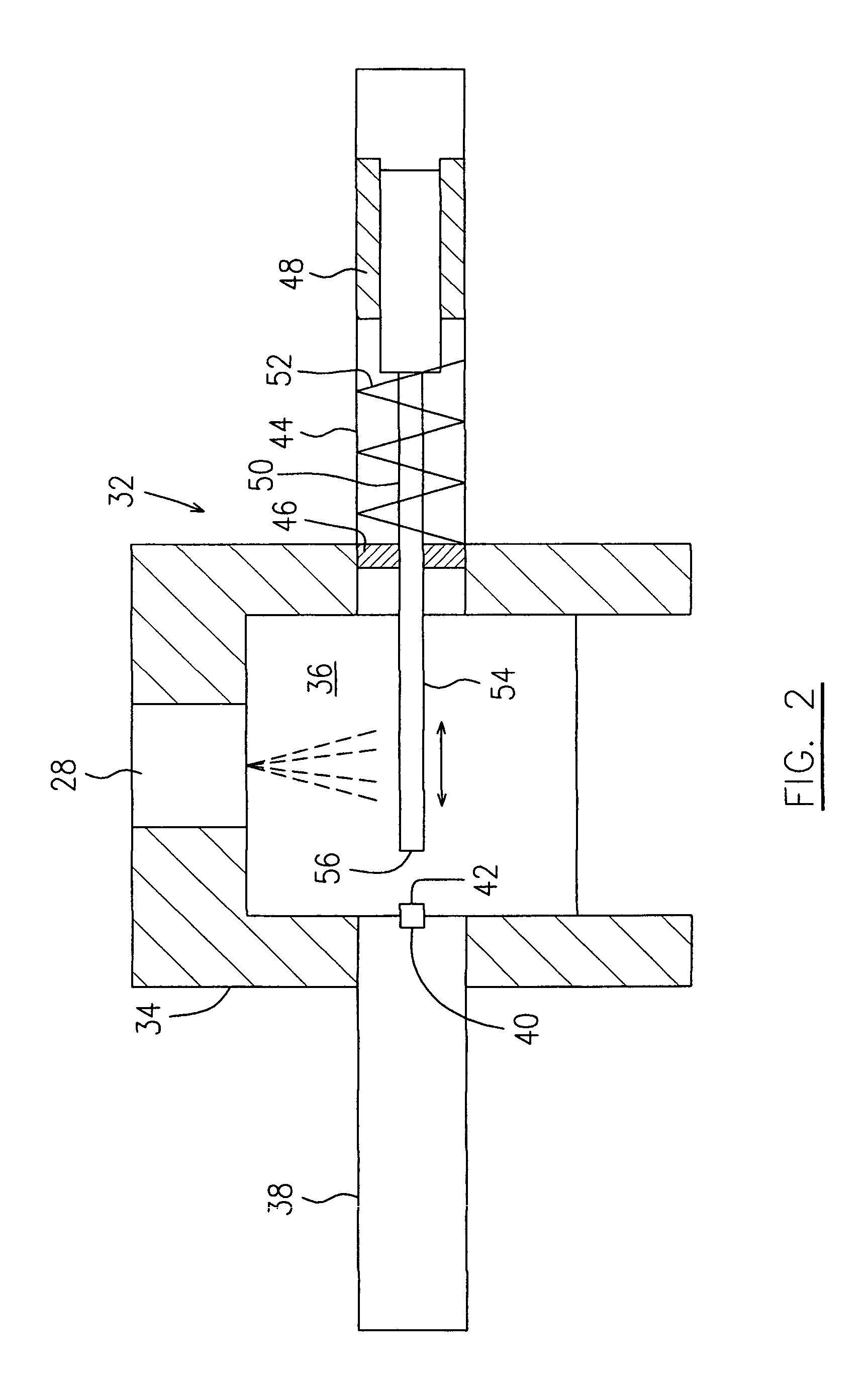
[0016]A continuous plasma ignition system generally indicated by numeral 32 is provided in one location of the annular combustor 26 downstream of one of the fuel injectors 28, for initiating a torch ignition process to start th...


PUM

PropertyMeasurementUnit
electric voltageaaaaaaaaaa
gap sizeaaaaaaaaaa
sizeaaaaaaaaaa

Abstract

A variable arc gap plasma igniter element includes electrodes moveable relative to each other. The electrodes are preferably set to define a smaller air gap to initiate a plasma arc and later extended to obtain longer plasma arc.

Description

FIELD OF THE INVENTION[0001]The present invention relates to an ignition system and more particularly to a continuous plasma ignition system for a gas turbine engine.BACKGROUND OF THE INVENTION[0002]An ignition system for a gas turbine engine may include a plasma igniter. A plasma arc is generated across an air gap between two electrodes to light fuel in a combustion chamber. The size of the air gap between the two electrodes is a problematic in igniter design. Larger air gaps provide plasma arcs with higher energy but require higher breakdown voltages which can lead to failure in other locations such as at lead connections. Smaller gaps are subject to short circuit if carbon accumulates in the gap.[0003]Therefore, there is a need for an improved plasma igniters.SUMMARY OF THE INVENTION[0004]One object of the present invention is to provide an improved plasma igniter for gas turbine engines.[0005]In accordance with one aspect of the present invention, there is a variable arc gap pla...

Claims


Application Information

Patent Timeline
Patent Type & Authority Patents(United States)
IPC IPC(8): B23K10/00B23K9/02F02C7/264
CPCF02C7/264F23D2207/00
Inventor PROCIW, LEV ALEXANDERGAUDET, DANY CLARENCE
Owner PRATT & WHITNEY CANADA CORP
Why Eureka
Try Eureka