
Spark plug

a technology of spark plugs and noble metals, applied in spark plugs, basic electric elements, electric devices, etc., can solve the problems of increasing the amount of heat applied to the ground electrode of the spark plug, cracking or separation of the joint between the materials, and increasing the cross-sectional area of the heat radiation passage. , the ignition performance of the spark plug may deteriorate, and the noble metal member can be enhanced

Active Publication Date: 2011-10-25
NGK SPARK PLUG CO LTD
View PDF13 Cites 11 Cited by
  • Summary
  • Abstract
  • Description
  • Claims
  • Application Information

AI Technical Summary

Benefits of technology

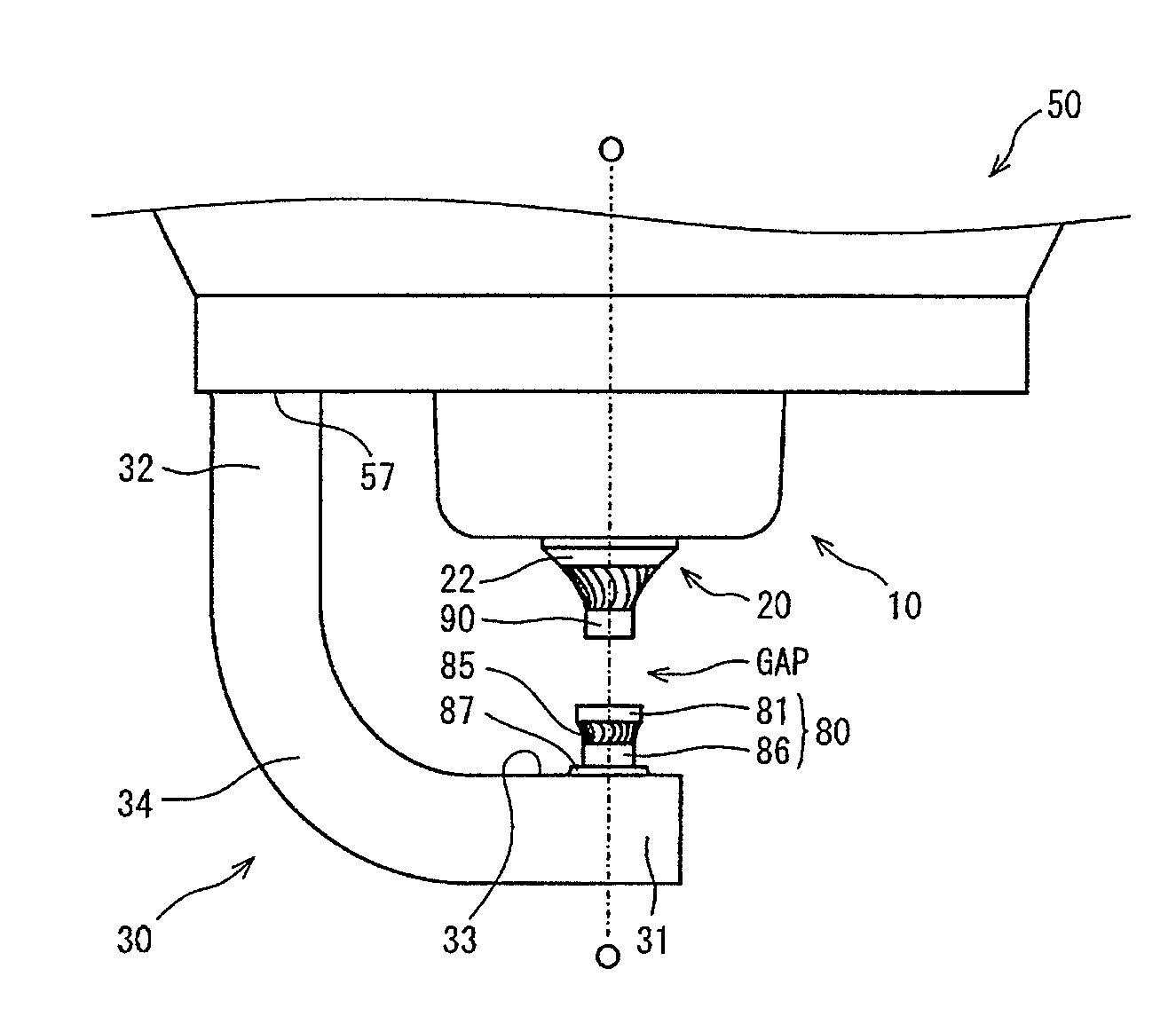
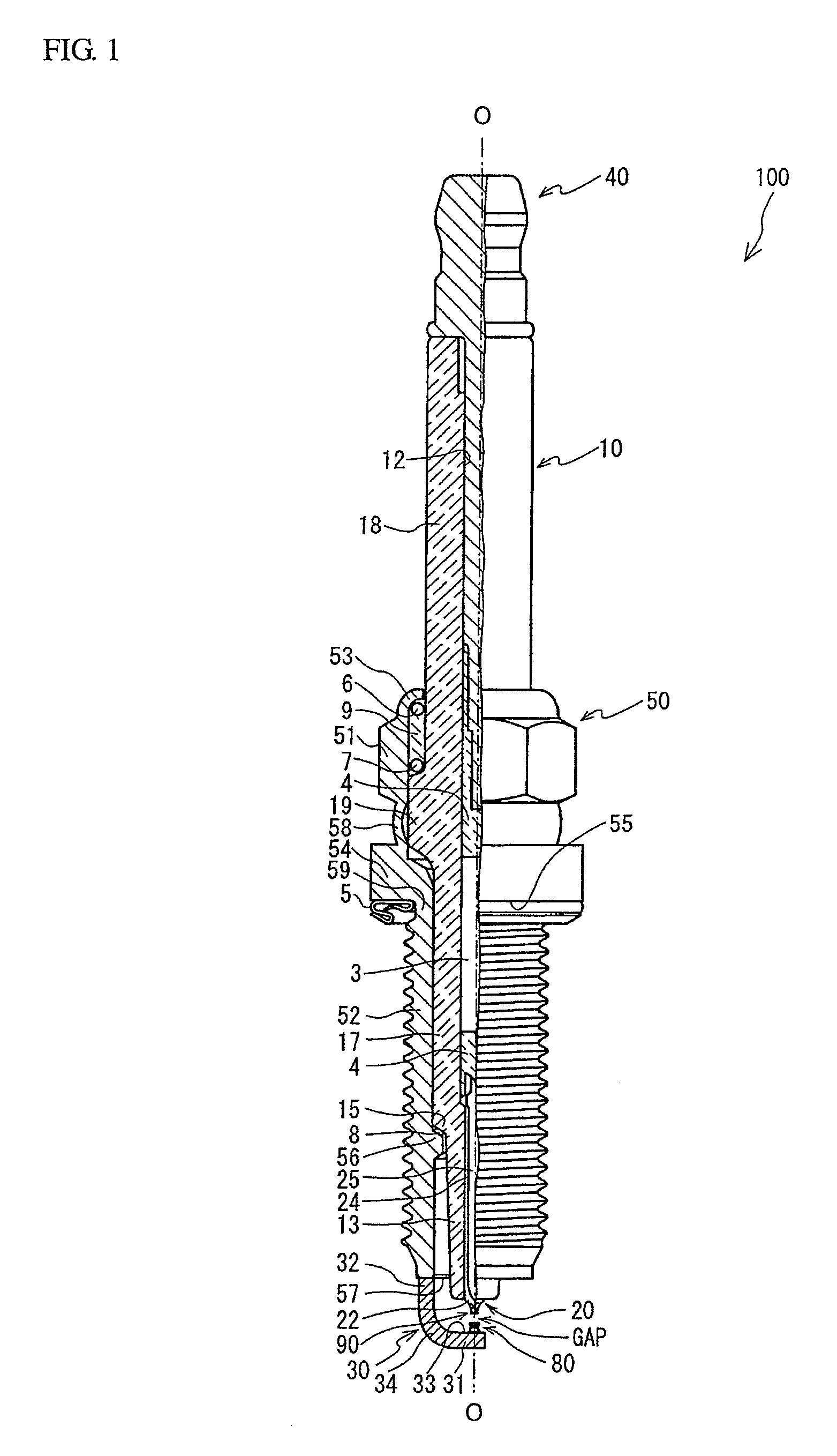
The present invention relates to a spark plug with a needle-like shaped spark section that is designed to improve ignition performance and reduce quenching effects. The needle-like shaped spark section is joined to the ground electrode and bent in a way that its side surface faces the front end portion of the center electrode. This design helps to limit heat radiation from the noble metal member and increase the temperature in the vicinity of the spark gap, reducing the quenching effect. The invention also addresses the issue of thermal load and provides a solution to improve ignition performance under retard ignition control.

Problems solved by technology

However, there is a large difference between the linear expansion coefficient of the noble metal and the liner expansion coefficient of e.g. nickel-based alloy material commonly used for the ground electrode.
If these materials are simply joined together, a crack or separation may occur in the joint between the materials under the influence of thermal load by cooling / heating cycles.
This leads to an increase in the amount of heat applied to the ground electrode of the spark plug and an increase in the influence of thermal load applied to the spark section by cooling / heating cycles.
As the noble metal member gets heated to a high temperature, it becomes likely that the noble metal member will be consumed by oxidation to cause a deterioration of spark wear resistance.

Method used


Image

  • Spark plug
  • Spark plug
  • Spark plug

Examples


experiment 1

[0049]First, an evaluation test was conducted to verify the relationship between the ignition performance and the thermal conductivity of the intermediate member of the spark section. For this evaluation test, eight kinds of materials (N40, N35, N30, N25, N20, N15, N10 and N5) containing Ni as a main component and having different thermal conductivities were prepared for production of intermediate members. The compositions of the respective materials are indicated in TABLE 1.

[0050]

TABLE 1Material ofComposition of intermediateThermalintermediatemember [wt %]conductivitymemberNiSiCrMnFeAlC[W / (m · K)]N40balance0.70.20.2—10.0240(97.88)N35balance1.20.20.2—2.20.0235(96.18)N30balance1.510.3—2.50.0230(94.68)N25balance1.51.52——0.0225(94.98)N20balance1.52230.50.0220(90.98)N15balance0.2160.38—0.0215(75.48)N10balance0.1250.1102.30.0210(62.48)N5 balance2302103.50.025(52.48)

[0051]As indicated in TABLE 1, the materials were prepared by mixing different contents of Si, Cr, Mn, Fe, Al and C (not usi...

experiment 2

[0058]The same verification test was also conducted on the case of the noble metal member having a different thermal conductivity from that of Experiment 1. For this test, eight types of samples A21 to A28 of spark sections were produced by forming the same eight types of intermediate members as above from the above materials N40 to N5, forming noble metal members from Pt-10Ni (thermal conductivity: 27.8 W / (m·K)) and joining the noble metal members to the intermediate members, respectively. The sizes of the noble metal members and the intermediate members were the same as above. Further, a sample A29 (current product) of a spark section was formed as a reference for evaluation in the same manner as above using only a noble metal member of Pt-10Ni. The samples of A21 to A29 were attached to spark plugs for test uses. The same evaluation test procedure was conducted on each of the samples A21 to A29. The test results are indicated in TABLE 3.

[0059]

TABLE 3Thermal conductivityMaterial o...

experiment 3

[0062]Next, an evaluation test was conducted to verify the relationship between the spark wear resistance and the thermal conductivity of the intermediate member of the spark section. For this evaluation test, spark plugs having the same samples A21 to A29 as those of Experiment 2 were produced. Each of the spark plugs with the samples A21 to A29 was mounted on a 2.0-liter, 4-cylinder gasoline engine and tested by driving the engine under the conditions of 5000 rpm and WOT (full throttle) for 400 hours according to bench durability test procedure. The size of the spark gap GAP of each sample was measured after the durability test. Then, the difference between the initial size (1.1 mm) and the measured size of the spark gap GAP (i.e. the amount of consumption of the noble metal member by spark discharges) was determined. The test results are indicated in TABLE 4.

[0063]

TABLE 4Thermal conductivityMaterial of[W / (m · K)]ConsumptionintermediateNoble metalIntermediateof noble metalSpark we...


PUM


Abstract

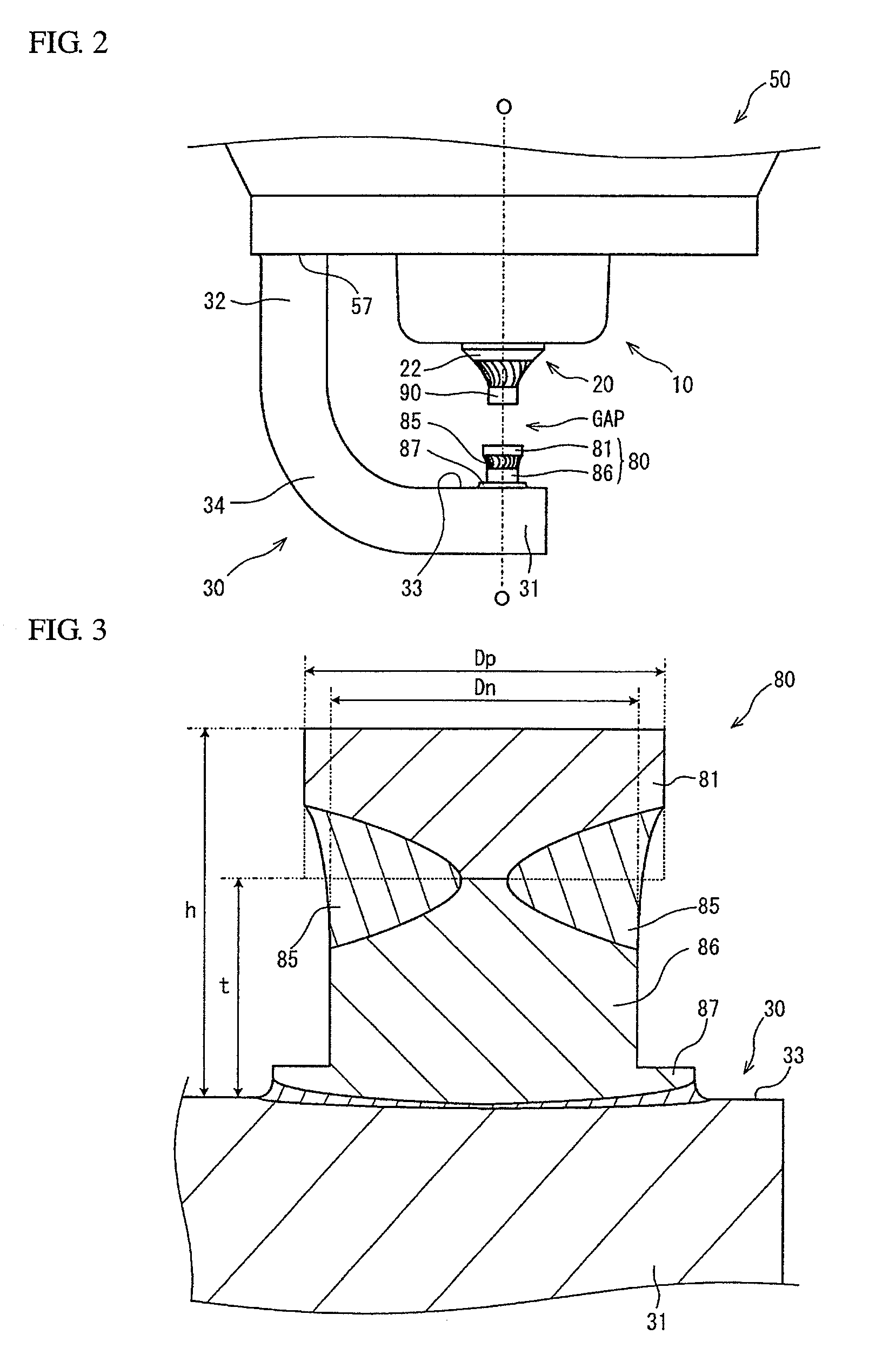
There is provided a spark section (80) of needle-like shape protruding from an inner surface (33) of a ground electrode (30) to define a spark gap between the spark section and an electrode tip on a center electrode. The spark section (80) has a noble metal member (81) and an intermediate member (86) joined to each other. The materials of the noble metal member (81) and the intermediate member (86) are selected in such a manner that the thermal conductivity of the intermediate member (86) is lower than that of the noble metal member (81). This limits heat radiation through the heat radiation passage from the noble metal member (81) through the intermediate member (86) to the ground electrode (30) so as to maintain the noble metal member (81) at a higher temperature than conventional types and reduce a quenching effect of the noble metal member (81) on a flame core generated in the spark gap for improvement in ignition performance.

Description

TECHNICAL FIELD[0001]The present invention relates to a spark plug in which a needle-like shaped spark section is disposed on a ground electrode to define a spark gap between the spark section and a center electrode.BACKGROUND ART[0002]A spark plug is known, which includes a center electrode, a ground electrode and a needle-like shaped spark section disposed on an inner surface (one side surface) of an end portion of the ground electrode facing the center electrode so as to define a spark gap between the spark section and the center electrode. (See e.g. Patent Document 1.) Herein, the needle-like shaped spark section refers to that, for example, having a protrusion length of 0.6 to 1.6 mm from the inner surface of the ground electrode and an outer diameter (or protruding end face diameter) of 0.5 to 1.2 mm. The spark plug with such a needle-like shaped spark section allows the ground electrode to be located away from the spark gap and reduces the tendency that a flame core generated...

Claims


Application Information

Patent Timeline
Patent Type & Authority Patents(United States)
IPC IPC(8): H01T13/20
CPCH01T13/39
Inventor MUSASA, MAMORUMIYASHITA, NAOMICHITORII, KAZUYOSHI
Owner NGK SPARK PLUG CO LTD
Learn More