Electrical system, voltage reference generation circuit, and calibration method of the circuit
a voltage reference and circuit technology, applied in the direction of electric variable regulation, temperature compensation modification, electric vehicles, etc., can solve the problem of increasing the cost of the manufacturing process
- Summary
- Abstract
- Description
- Claims
- Application Information
AI Technical Summary
Benefits of technology
Problems solved by technology
Method used
Image
Examples
first embodiment
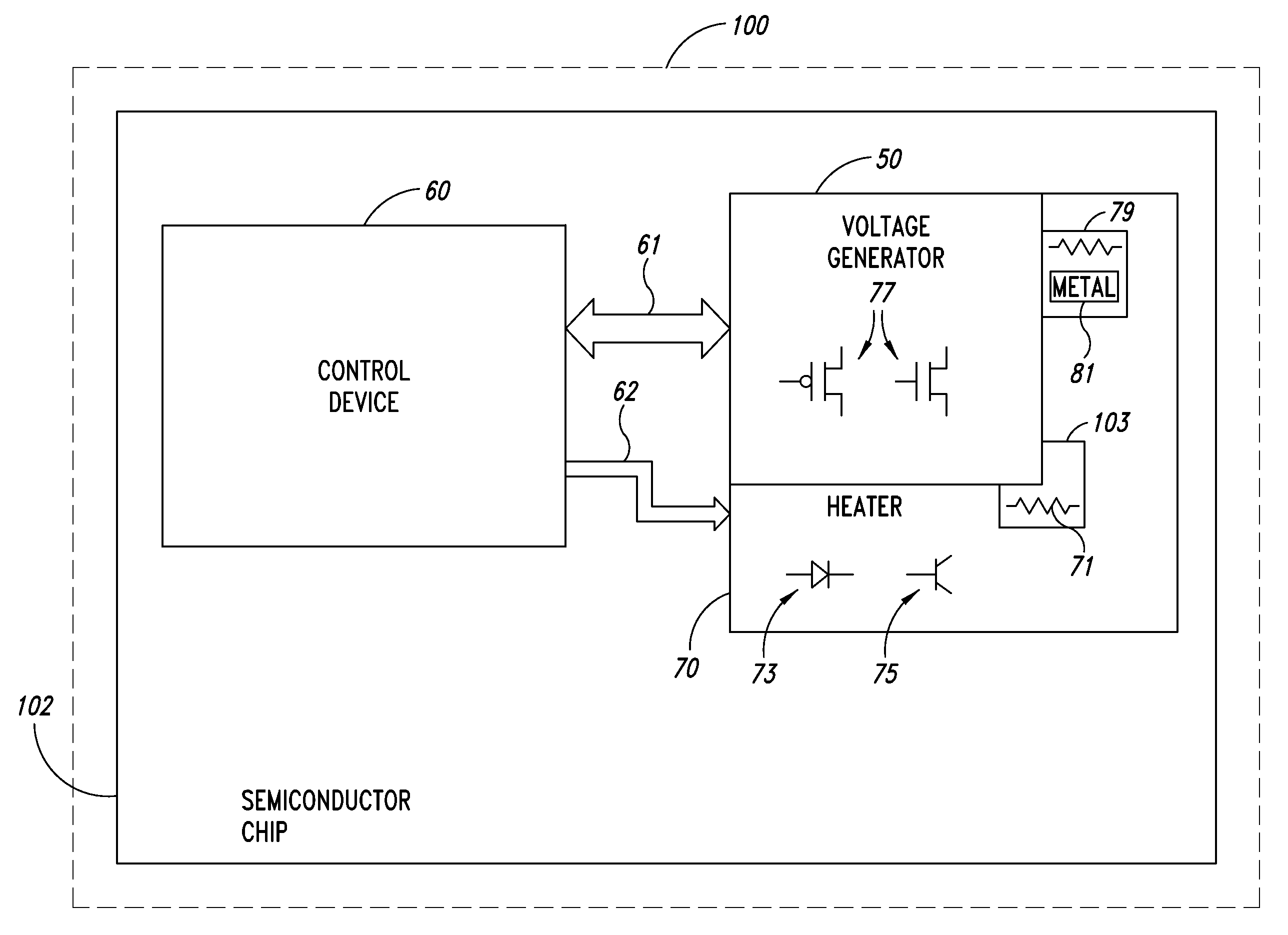
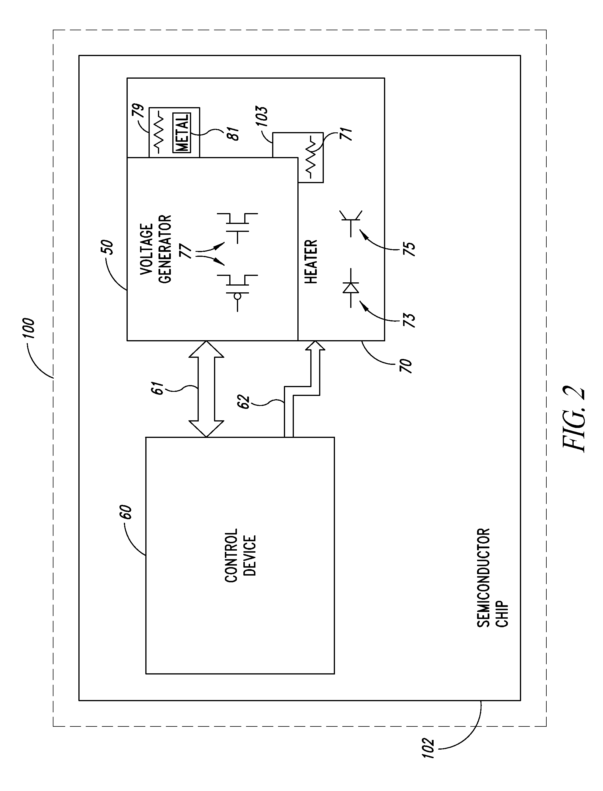
[0046]FIG. 4 shows schematically the voltage reference generation circuit 100 in which the control device 60 comprises a control logic 63, a register 64, and a sample and hold device 65. The control logic 63 is configured to send command signals to the heater 70 on the command line 62 and calibration signals carrying the calibration words to the band-gap voltage reference circuit 50 on a calibration bus 61A. Moreover, control logic 63 is configured to receive by a bus 61C samples representing the voltage generated by the band-gap voltage reference circuit 50. The control logic 63 can be implemented by a combinatory network and / or by a sequential network and operates according to a suitable algorithm in order to chose the calibration words that minimize variations with temperature of the voltage generated by the band-gap voltage reference circuit 50.
[0047]The sample and hold device 65 is configured to receive a voltage signal generated by the band-gap voltage reference circuit 50 and...
second embodiment
[0058]FIG. 7 shows the voltage reference generation circuit 100 wherein the control device 60 is different from the one depicted in FIG. 4 and includes the control logic 63, the register 64, a comparator 80 and a comparison voltage generator 90. The comparison voltage generator 90 is a generation circuit identical or substantial identical to the voltage generator circuit 50 and, in particular, is a further band-gap voltage reference circuit. The comparison voltage generator 90 can be activated and deactivated by the control logic 63 and, according to the example described, is not heated during the calibration process. Particularly, the comparison voltage generator 90 is thermally isolated from said heater 70.
[0059]The comparator 80 can be realized in a traditional manner by using analogical components and is activated by the control logic 63 during the comparison process to compare the voltage signal provided by the voltage generator circuit 50 with the one provided on a bus 91 by t...
PUM
 Abstract
Description
Claims
Application Information
 - R&D
- Intellectual Property
- Life Sciences
- Materials
- Tech Scout
- Unparalleled Data Quality
- Higher Quality Content
- 60% Fewer Hallucinations
Browse by: Latest US Patents, China's latest patents, Technical Efficacy Thesaurus, Application Domain, Technology Topic, Popular Technical Reports.
© 2025 PatSnap. All rights reserved.Legal|Privacy policy|Modern Slavery Act Transparency Statement|Sitemap|About US| Contact US: help@patsnap.com


