Laser scanning microscope

a scanning microscope and laser technology, applied in the field of laser scanning microscopes, can solve the problems of complicated circuit configuration, complicated circuit configuration, and complicated circuit configuration, and achieve the effect of simplifying circuit configuration and complex circuit configuration

Active Publication Date: 2011-10-25
NIKON CORP
View PDF2 Cites 2 Cited by
  • Summary
  • Abstract
  • Description
  • Claims
  • Application Information

AI Technical Summary

Problems solved by technology

However in the case of prior art including Patent Document 1, laser lighting control and image capturing control are implemented by hardware, so supporting complicated combinations of control signals to perform these controls is difficult.
According to the conventional hardware-based systems that are used, it is easy to create one set of control signals for one cycle of scanning, but to create a plurality of sets of control signals complicates the circuit configuration since different hardware must be provided for each set.
Also a new mechanism to change the predetermined timing on the hardware must be installed to adjust these control signals, which makes the circuit configuration even more complicated.
The circuit configuration cannot be changed after the circuit is designed, which means that an arbitrary control signal cannot be generated once design is completed.

Method used


Image

  • Laser scanning microscope
  • Laser scanning microscope
  • Laser scanning microscope

Examples


Embodiment Construction

[0035]Embodiments of the present invention will now be described with reference to the drawings.

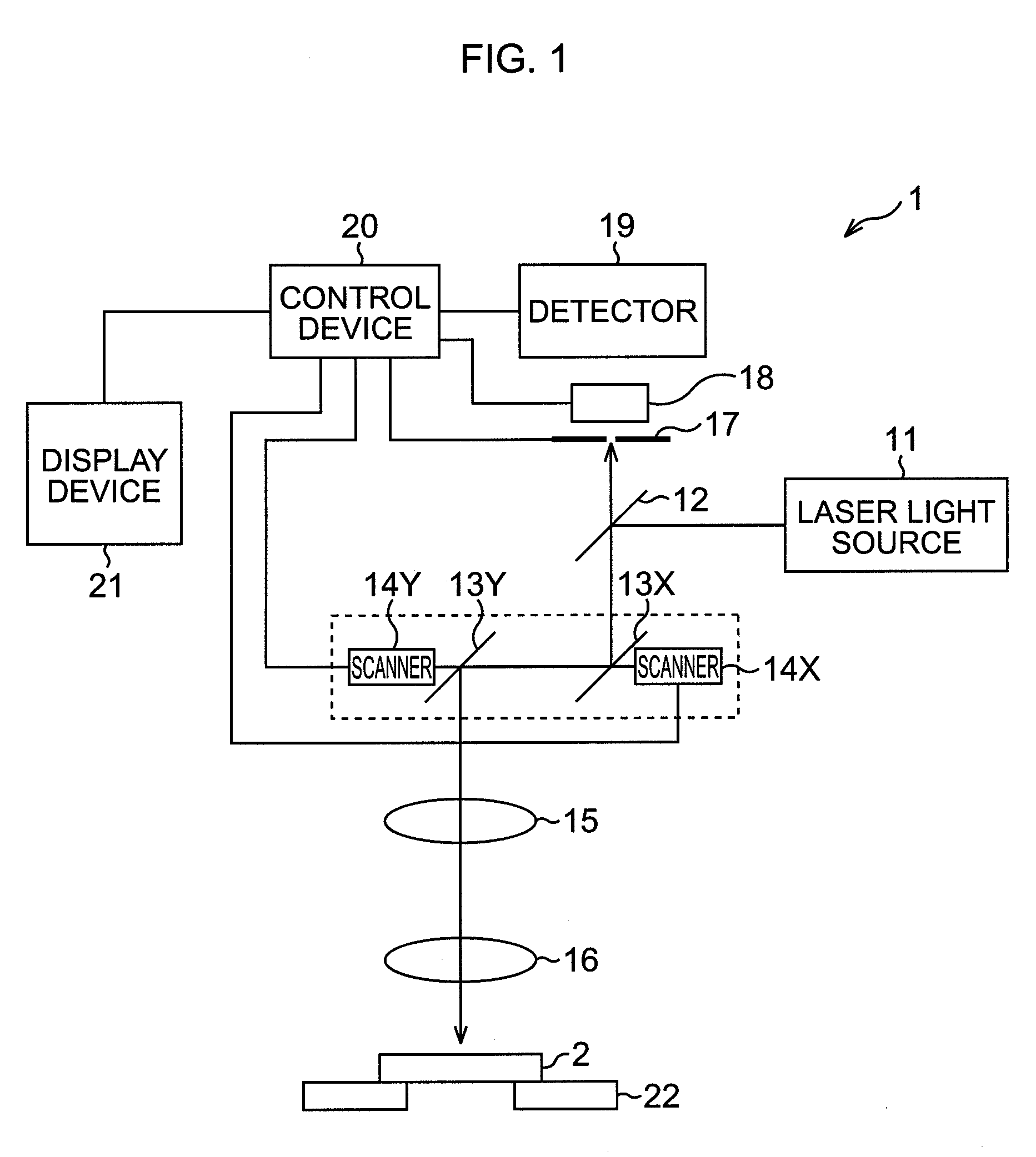
[0036]FIG. 1 is a diagram depicting an embodiment of an optical system of a confocal laser scanning microscope 1 to which the present invention is applied. The operation of the optical system of the confocal laser scanning microscope 1 will be described.

[0037]The laser light (excited light) emitted from the laser light source 11 is guided to a scanner optical system via an optical fiber (not illustrated) of which output end is connected to the fiber connector (not illustrated). The laser light guided into the scanner optical system is reflected in a direction to a mirror 13X by a dichroic mirror 12. The laser light reflected in a direction to the mirror 13X is reflected in a direction to a scanning lens system 15 by the mirror 13X and the mirror 13Y. The laser light is condensed by being transmitted through the scanning lens system 15 and the objective lens 16, and is irradiated onto a sa...


PUM


Abstract

The present invention relates to a laser scanning microscope that can generate an arbitrary control signal without depending on the configuration of the hardware. A memory 64 has a bit width wider than a bit width of drive data based on a drive table for generating a drive signal X for driving a scanner, which is driven by a drive circuit 66X, to scan a designated scanning area at a designated speed, and stores the drive table, and a controller 61 sets a control signal for controlling a predetermined operation in a predetermined mechanism that has a strict time relationship with the scanning based on the drive data, in bits in the bit width of the memory 64X, excluding the bits used by the drive data, and these mechanisms perform the predetermined operation based on the control signal that is read simultaneously when the drive data is read from the memory 64X. The present invention can be applied to a confocal laser scanning microscope that observes a sample by performing scanning with laser light.

Description

TECHNICAL FIELD[0001]The present invention relates to a laser scanning microscope, and more particularly to a laser scanning microscope that can observe a sample by performing scanning with laser light with a simplified hardware configuration.BACKGROUND ART[0002]In conventional laser scanning microscopes, a reflecting element, such as a galvano scanner, is disposed on an optical path between a laser light resource and an objective lens, and the sample is scanned by the laser light by changing the rotation angle of this reflecting element continuously (e.g. see Patent Document 1).[0003]In the case of a laser scanning microscope, reading the scan data on scanning systems and control signals, for performing image capture control and laser control, are normally constructed as independent systems synchronizing with a common reference clock. In Patent Document 1, for example, the scanner control circuit and the image sampling circuit are constructed as independent systems that synchronize...

Claims


Application Information

Patent Timeline
Patent Type & Authority Patents(United States)
IPC IPC(8): G02B21/00
CPCG02B21/008
Inventor KISHIMOTO, HIROSHI
Owner NIKON CORP
Why Eureka
Try Eureka