Enhanced sample imaging using structured illumination microscopy

A technology for microscope objective lenses and samples, applied in microscopes, optical devices, optical radiation measurement, etc., can solve the problems that SIM systems cannot be compatible with confocal microscopes, and confocal microscopes cannot be irradiated once, etc., to improve spatial resolution and reduce costs. , the effect of improving image quality

Pending Publication Date: 2021-11-26
热电科学仪器有限公司
View PDF0 Cites 0 Cited by
  • Summary
  • Abstract
  • Description
  • Claims
  • Application Information

AI Technical Summary

Problems solved by technology

[0010] Because confocal microscopes cannot illuminate the entire sample at once as in the case of widefield microscopy, existing SIM systems and their reconstruction algorithms are not directly "embedded" compatible with confocal microscopes

Method used


Image

  • Enhanced sample imaging using structured illumination microscopy
  • Enhanced sample imaging using structured illumination microscopy
  • Enhanced sample imaging using structured illumination microscopy

Examples


example 1

[0056] simulation study

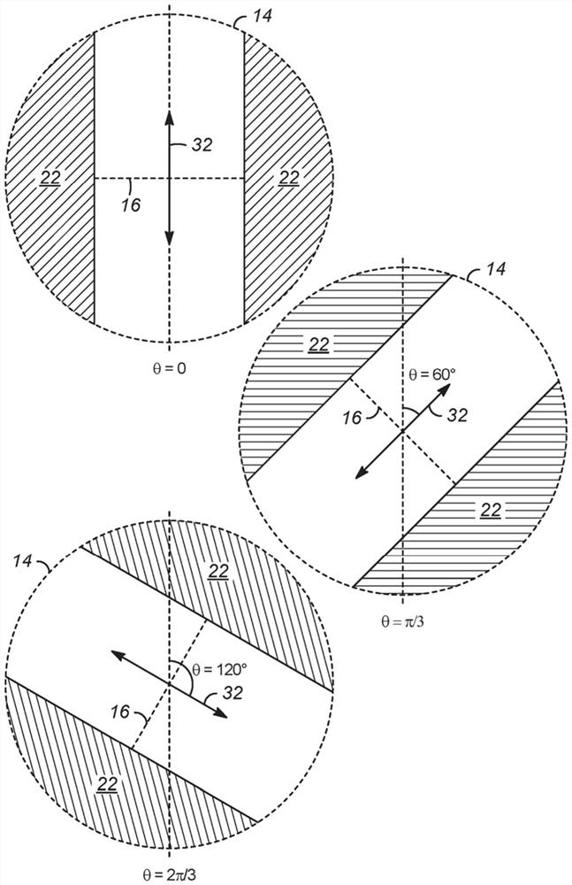
[0057]Imaging of real samples with "ground-truth images" was simulated using confocal SIM according to the modified imaging method described in this paper and compared with conventional CLSM. Simulation results were obtained using the light propagation library available online as "PROPER". This suite of programs for simulating the propagation of light through optical systems using Fourier transform algorithms (Fresnel, angular spectrum) has been thoroughly validated as a physical optics propagation tool and is commonly used by astronomers for telescopes. performance modeling. This library is used to simulate, in particular, the confocal and confocal SIM point spread functions of a 532nm laser passing through a 100x, 0.7NA objective lens and focusing through a 75mm focal length lens into a 25μm confocal pinhole. image 3 The simulated point spread function of this confocal SIM example is plotted for three different angles of the beam (0, π / 3, 2π / 3)...

example 2

[0060] Experiment demonstration

[0061] according to figure 2 With the configuration shown, a prototype microscope was built for performing confocal SIM. The dichroic mirror provides the ability to observe the laser spot on the sample using the microscope camera. This camera was used to acquire spot images from the SLM generated by the SIM pattern to demonstrate that the same focused fringe pattern as in the physical optics propagation simulation study described in Example 1 was generated. This is based on a side-by-side comparison with simulation results, taking into account the circular border around the images acquired in this experimental demonstration to help indicate approximate alignment with the confocal pinhole. In the simulation studies, the simulated SIM laser patterns have taken into account the application of confocal masks, which is why the outer shapes of these patterns are circular, as in image 3 shown.

[0062] Use Pelcotec TM CDMS (Critical Dimensio...


PUM

PropertyMeasurementUnit
diameteraaaaaaaaaa

Abstract

Methods and apparatuses are disclosed whereby structured illumination microscopy (SIM) is applied to a scanning microscope, such as a confocal laser scanning microscope or sample scanning microscope, in order to improve spatial resolution. Particular aspects of the disclosure relate to the discovery of important advances in the ability to (i) increase light throughput to the sample, thereby increasing the signal / noise ratio and / or decreasing exposure time, as well as (ii) decrease the number of raw images to be processed, thereby decreasing image acquisition time. Both effects give rise to significant improvements in overall performance, to the benefit of users of scanning microscopy.

Description

[0001] Cross References to Related Applications [0002] This application claims priority to U.S. Patent Application Serial No. 62 / 827,921, filed April 2, 2019, the entire contents of which are incorporated herein by reference for all purposes. technical field [0003] The present invention relates to imaging samples using scanning microscopes (eg, confocal laser scanning or sample scanning microscopes) and structured illumination for enhanced resolution. Background technique [0004] Conventional optical microscopy has diffraction-limited spatial resolution. When the back aperture of the microscope objective is completely filled with collimated light, the image in the focal point, or sample plane, is an Airy disk with radius r according to airy (in nanometers nm): [0005] [0006] where λ (in nm) is the illumination wavelength and NA (dimensionless) is the numerical aperture of the microscope objective and provides a measure of its resolving power. Related to this q...

Claims


Application Information

Patent Timeline
Patent Type & Authority Applications(China)
IPC IPC(8): G01N21/64G01N21/65G01B11/25
CPCG01N21/6458G01N21/65G01N2201/0675G01J1/0437G01J1/4257G01J3/0229G01J3/10G01J3/06G01J3/0218G01J3/2823G01J3/44G01J1/0425G02B21/0076G02B21/0056G02B21/0032G02B21/367G02B21/006G02B21/008G02B21/0072G01N21/658G01J3/4412
Inventor M·乔治亚迪斯F·德克
Owner 热电科学仪器有限公司
Why Eureka
Try Eureka