
Multi-transceiver architecture for advanced Tx antenna monitoring and calibration in MIMO and smart antenna communication systems

a communication system and multi-transceiver technology, applied in the field of multi-transceiver architectures, to achieve the effect of worse performan

Inactive Publication Date: 2011-10-25
RPX CORP
View PDF4 Cites 56 Cited by
  • Summary
  • Abstract
  • Description
  • Claims
  • Application Information

AI Technical Summary

Benefits of technology

This approach enables efficient calibration and diagnostics of smart antenna systems, reducing costs and complexity by allowing for internal calibration and improved signal quality monitoring, enhancing the accuracy and reliability of beamforming and data transmission.

Problems solved by technology

These in dependent data streams, however, can interfere with each other such that a complex channel equalizer is required at the wireless receiver side in order to separate RF signals received via different signal propagation paths.

Method used


Image

  • Multi-transceiver architecture for advanced Tx antenna monitoring and calibration in MIMO and smart antenna communication systems
  • Multi-transceiver architecture for advanced Tx antenna monitoring and calibration in MIMO and smart antenna communication systems
  • Multi-transceiver architecture for advanced Tx antenna monitoring and calibration in MIMO and smart antenna communication systems

Examples


Embodiment Construction

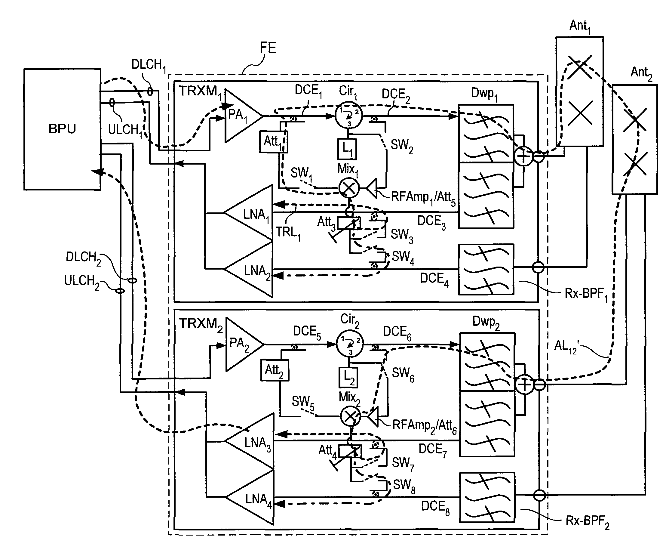
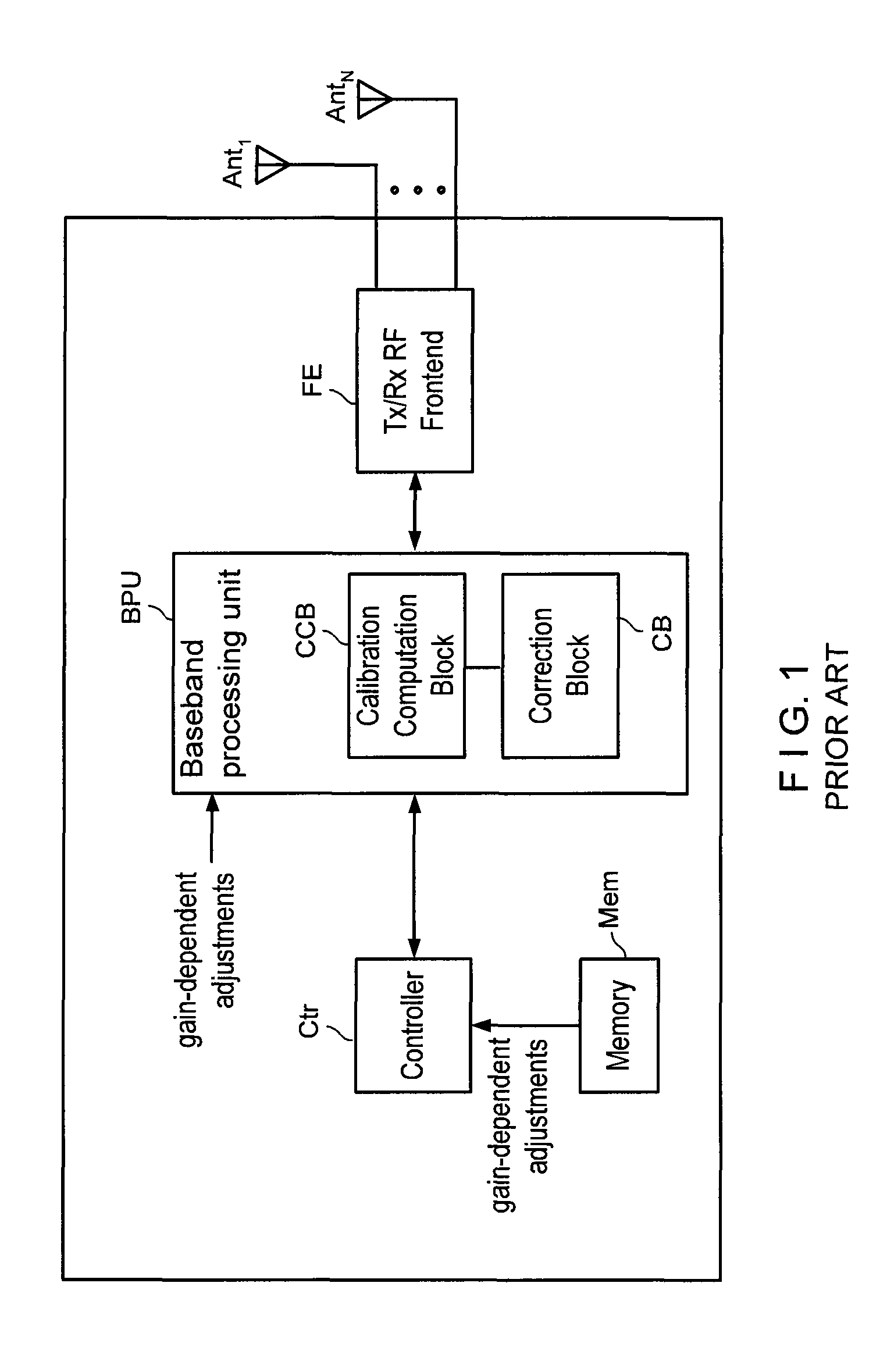
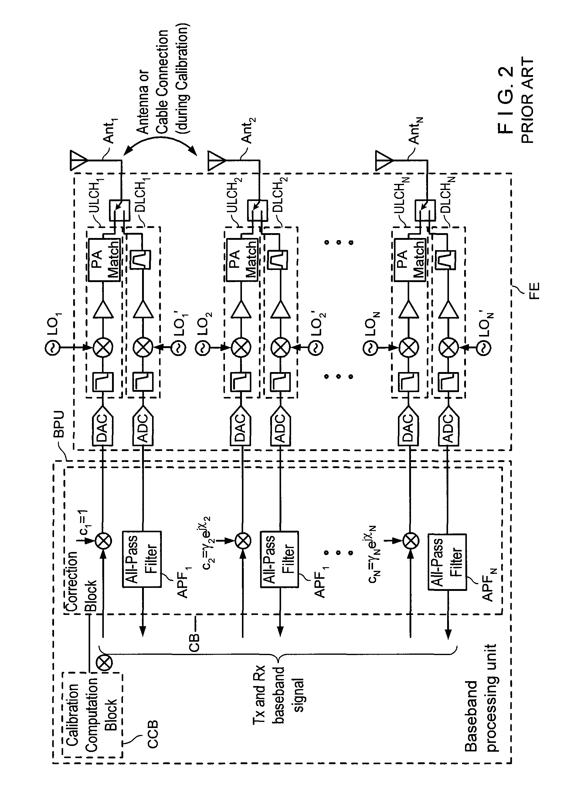
[0007]One of the challenges in the implementation of a smart antenna or MIMO system can be that there are several sources of timing, phase and amplitude uncertainties which should be compensated in start-up and during normal operation of the system. Such exemplary uncertainties can be due to reset-to-reset variation of delays in the digital parts of the complex system and due to thermal drift and aging in the analog parts of the system. Exemplary embodiments of the present invention provide a method for calibrating specially the downlink signal paths of a smart antenna or MIMO base station in production and during runtime operation. The exemplary method may also be used for diagnosis of separate signal paths and signal quality.

[0008]Antenna looping between different transceiver modules of a wireless transceiver device with spatial antenna diversity for use in a smart antenna or MIMO base station normally requires external systems components in addition to “ordinary” RF front ends an...


PUM


Abstract

Exemplary embodiments of system and method are provided for measuring signal amplitude, phase and / or delay offsets between multiple transmit signals fed through the transmit signal processing chains and wirelessly transmitted over the transceive antennas of separate transceiver modules, wherein transmit signal coupling between the transmit antennas of said transceiver modules' transmit signal processing chains may be used for synchronizing the transmit signals and calibrating their amplitude, phase and / or delay parameters. The exemplary embodiments further provide a front end arrangement of a wireless transceiver device which can comprise at least two independently controllable transceiver modules, each connected to an associated spatial diversity transceive antenna and comprising at least one associated transmit signal processing chain and at least one associated receive signal processing chain coupled to a common baseband processing unit. The exemplary transceiver architecture can be executed on an antenna loop between the transmit signal processing chain of a first transceiver module and the transmit signal processing chain of a second transceiver over the air interface and relies on an adaptive antenna concept which facilitates a wireless transmission of data via a plurality of wireless communication channels utilizing an array of transceive antennas, receiving feedback information via at least one of said communication channels using such antenna loop and modifying a transmission mode based on the received feedback information.

Description

FIELD OF THE INVENTION[0001]Exemplary embodiments of the present invention relates to the field of multi-transceiver architectures for use in a multiple-input multiple-output (MIMO) spatial multiplexing system or smart antenna system with adaptive beamforming and advanced transmit (Tx) signal monitoring capability. More particularly, the exemplary embodiments of the present invention refers to a system and method for measuring signal amplitude, phase and / or delay offsets between multiple transmit signals fed through the Tx signal processing chains and wirelessly transmitted over the Tx / Rx antennas of separate transceiver modules.BACKGROUND INFORMATION[0002]It is possible to apply the principles of the exemplary embodiments of present invention to the scope of MIMO spatial multiplexing or smart antenna system with spatial diversity, adaptive beamforming and advanced Tx signal monitoring capability as provided herein. Thus, it may be beneficial to provide a brief overview of these sys...

Claims


Application Information

Patent Timeline
Patent Type & Authority Patents(United States)
IPC IPC(8): H04B15/00H04B17/00
CPCH04B17/364H04B17/21H04B17/327H04B17/14H04B7/0617H04B7/0697
Inventor MARTIKKALA, RISTOHEINIKOSKI, KAUKOADOLFSEN, PEKKA
Owner RPX CORP
Learn More