Actuator assembly for prosthetic or orthotic joint

actuator technology, applied in the field of systems and methods for controlling a prosthetic or orthotic joint, can solve the problems of high energy expenditure on the part of the disabled person or amputee, inability to take into account the dynamic conditions of the working environment of the basic controller, and inability to achieve the effect of reducing the risk of injury, and reducing the effect of the patient's li

Active Publication Date: 2011-11-01
OSSUR HF
View PDF225 Cites 114 Cited by
  • Summary
  • Abstract
  • Description
  • Claims
  • Application Information

AI Technical Summary

Benefits of technology

[0016]In one embodiment, a prosthetic or orthotic system is provided having an ankle-motion-controlled foot. The prosthetic or orthotic system comprises, among other things, a lower limb member, an actuator, and a foot unit. The actuator is configured to mimic the motion of an ankle by adjusting the angle between the lower limb member and the foot unit. The prosthetic or orthotic system also comprises an attachment portion that facilitates coupling of the lower limb member to another prosthetic or orthotic member, to the stump of an amputee, or to another component. The prosthetic or orthotic system may also comprise a rechargeable battery to provide power to the actuator or other components of the system. Embodiments of the invention include systems for both transtibial and transfemoral amputees.
[0033]In another embodiment, a system is disclosed for sensing a rotational movement of a lower-limb prosthetic device. The system includes a prosthetic foot and an attachment member having an upper end and a lower end. The system also includes a pivot assembly rotatably coupling the lower end of the attachment member to the prosthetic foot to allow for rotation of the prosthetic foot about a pivot axis extending through the pivot assembly, wherein the pivot assembly is configured to substantially mimic a natural ankle joint The system further includes a sensor assembly coupled to the pivot assembly and configured to detect the rotation of the prosthetic foot about the pivot axis, wherein at least a portion of the sensor assembly is configured to rotate about the pivot axis and is securely positioned along the pivot axis to substantially eliminate other movement.

Problems solved by technology

Such basic controllers do not take into consideration the dynamic conditions of the working environment.
The passive nature of these conventional prosthetic and orthotic devices typically leads to movement instability, high energy expenditure on the part of the disabled person or amputee, gait deviations and other short- and long-term negative effects.

Method used


Image

  • Actuator assembly for prosthetic or orthotic joint
  • Actuator assembly for prosthetic or orthotic joint
  • Actuator assembly for prosthetic or orthotic joint

Examples


Embodiment Construction

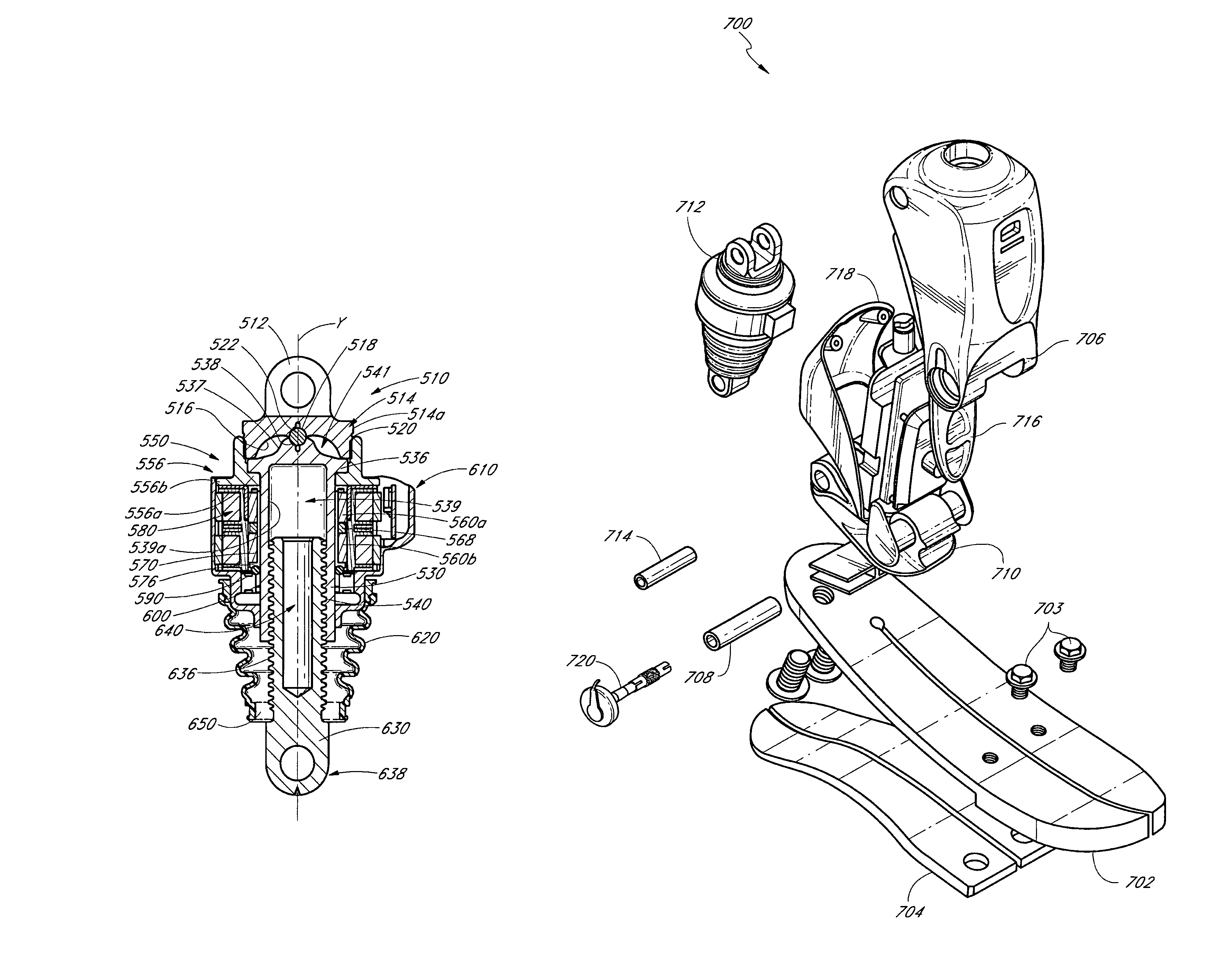
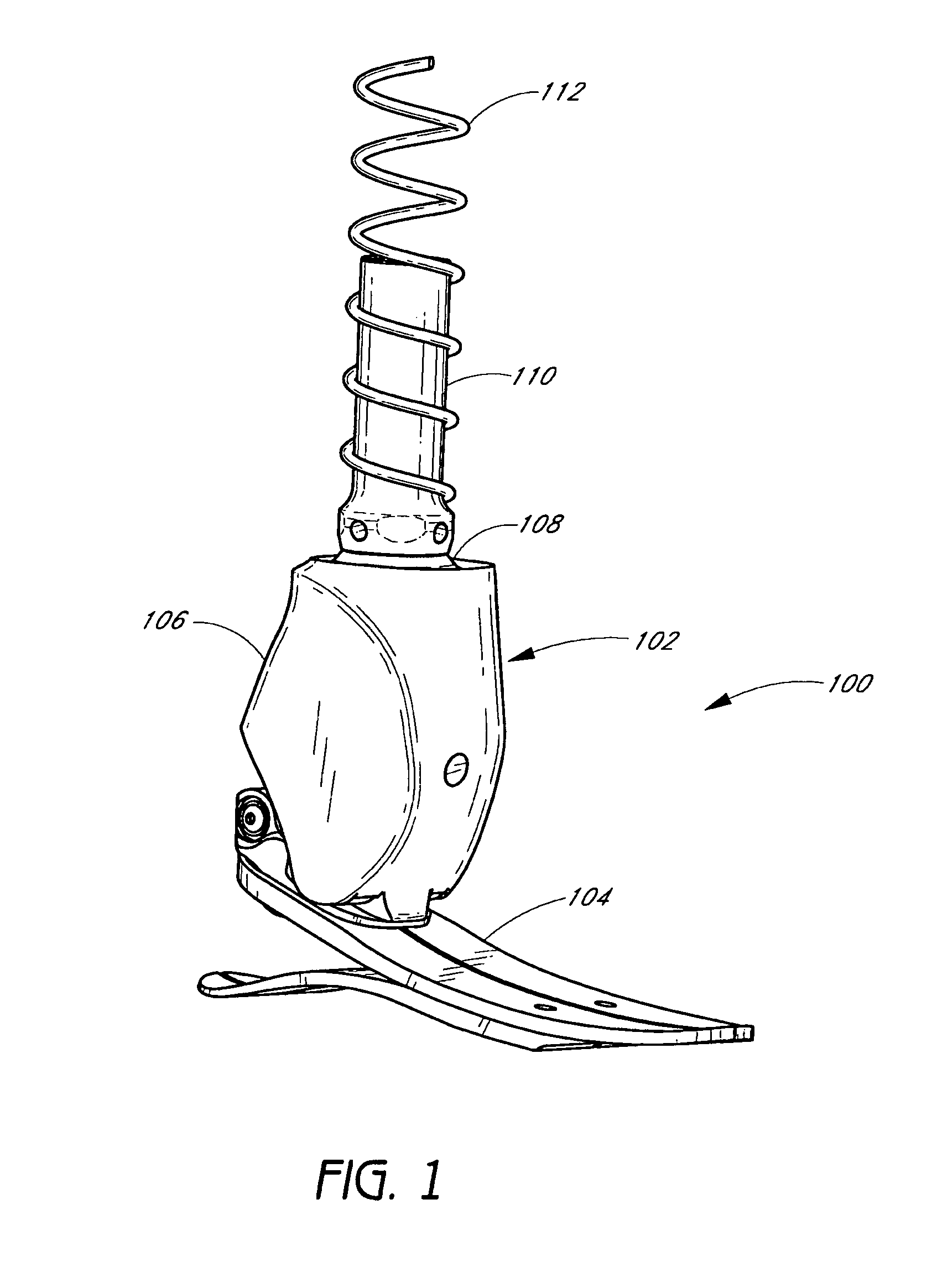
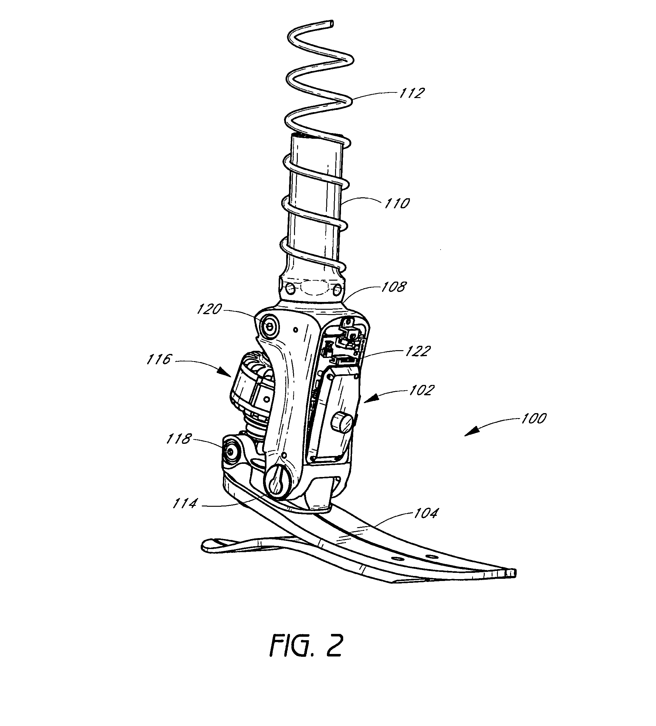
[0065]Some preferred embodiments of the invention described herein relate generally to prosthetic and orthotic systems and, in particular, to prosthetic and orthotic devices having an ankle-motion-controlled foot. While the description sets forth various embodiment-specific details, it will be appreciated that the description is illustrative only and should not be construed in any way as limiting the invention. Furthermore, various applications of the invention, and modifications thereto, which may occur to those who are skilled in the art, are also encompassed by the general concepts described herein.

[0066]The features of the system and method will now be described with reference to the drawings summarized above. Throughout the drawings, reference numbers are re-used to indicate correspondence between referenced elements. The drawings, associated descriptions, and specific implementation are provided to illustrate embodiments of the invention and not to limit the scope of the inven...


PUM


Abstract

A system and method associated with the movement of a limb. In one example, the system, such as a prosthetic or orthotic system, includes an actuator that actively controls, or adjusts, the angle between a foot unit and a lower limb member. The actuator preferably selectively locks during a desired phase in a gait cycle of the limb and minimizes friction against a rotor of the actuator. A processing module may control movement of the actuator based on data obtained from a sensor module. For instance, sensing module data may include information relating to the gait of a user and may be used to adjust the foot unit to substantially mimic the movement of a natural, healthy ankle. The system may further accommodate, for example, level ground walking, traveling up / down stairs, traveling up / down sloped surfaces, and various other user movements. In addition, the processing module may receive user input or display output signals through an external interface. For example, the processing module may receive a heel height input from the user.

Description

RELATED APPLICATIONS[0001]The present application is related to the following applications, each of which is incorporated herein by reference in its entirety and is to be considered a part of this specification:[0002]U.S. application Ser. No. 11 / 056,344, filed Feb. 11, 2005, and entitled “SYSTEM AND METHOD FOR MOTION-CONTROLLED FOOT UNIT”;[0003]U.S. application Ser. No. 11 / 057,391, filed Feb. 11, 2005, and entitled “SYSTEM AND METHOD FOR MOTION-CONTROLLED FOOT UNIT”;[0004]U.S. Provisional Application No. 60 / 544,259, filed Feb. 12, 2004, and entitled “LOWER LIMB PROSTHESIS WITH ANKLE-MOTION-CONTROLLED FOOT”; and[0005]U.S. Provisional Application No. 60 / 588,232, filed Jul. 15, 2004, and entitled “PROSTHETIC OR ORTHOTIC SYSTEM WITH ANKLE-MOTION-CONTROLLED FOOT.”BACKGROUND OF THE INVENTION[0006]1. Field of the Invention[0007]Preferred embodiments of this invention relate to systems and methods for controlling a prosthetic or orthotic joint, and in particular relates to a device and meth...

Claims


Application Information

Patent Timeline
Patent Type & Authority Patents(United States)
IPC IPC(8): A61F2/48A61F2/64A61F2/62A61F2/68
CPCA61F2/66A61F2/68A61F2/6607A61F2/72A61F2002/5018A61F2002/5073A61F2002/701A61F2002/6614A61F2002/705A61F2002/7625A61F2002/7635A61F2002/764A61F2002/7645A61F2002/704A61F2/60A61F2/604A61F2/64A61F2/70A61F2002/5016A61F2002/502A61F2002/5021A61F2002/5043
Inventor JONSSON, HELGICLAUSEN, ARINBJORN VIGGOINGIMARSSON, GUDNILECOMTE, CHRISTOPHESIGFUSSON, LARUSRAGNARSDOTTIR, HEIOR N GIGJA
Owner OSSUR HF
Why Eureka
Try Eureka