Method for pseudo-differential transmission using modal electrical variables

a technology of electrical variables and methods, applied in waveguide type devices, cross-talk reduction, line-transmission details, etc., can solve problems such as noise, method subject to two detrimental phenomena, and scheme is therefore vulnerable to external crosstalk

Inactive Publication Date: 2011-11-01
ZXNOISE LLC
View PDF14 Cites 227 Cited by
  • Summary
  • Abstract
  • Description
  • Claims
  • Application Information

AI Technical Summary

Benefits of technology

[0092]it provides very low reflections for all signals propagating inside said (n+1)-conductor multiconductor transmission line and incident on the termination circuit;
[0093]it does not reduce the reflections for the noise propagating in the circuit formed by the interconnection and the reference conductor.
[0138]means for optimizing the relative position of the transmission conductors and the return conductor by minimizing the error coefficient(s).
[0151]In a device for implementing the method of the invention, it is possible that each of said termination circuits is arranged at an end of said interconnection. This arrangement is preferred because specialists understand that it is the best technique for eliminating reflections of signals propagating in said (n+1)-conductor multiconductor transmission line.
[0165]According to the invention, at least one termination circuit is such that ZRL is a matrix of size n×n. This implies that this termination circuit in the activated state approximately behaves, for the interconnection, as if it was not connected to said reference conductor. However, a device for implementing the method of the invention may further comprise one or more damping circuits coupled to said return conductor, each of said damping circuits being, for said return conductor, approximately equivalent to a network consisting of a passive two-terminal circuit element connected in series with a voltage source delivering a constant voltage, said network having a first terminal coupled to said return conductor, said network having a second terminal coupled to said reference conductor (ground). Since the invention does not use signals applied between the return conductor and ground, the function of said damping circuits is not to reduce the reflections of signals. The specialist understands that said damping circuits are intended to provide a damping of the resonances of the circuit consisting of the return conductor and the reference conductor, which may be excited by the noise produced by unwanted electromagnetic couplings. Said damping circuits may therefore further reduce the effects of unwanted electromagnetic couplings.

Problems solved by technology

This method is subject to two detrimental phenomena: echo and crosstalk.
However, there are other crosstalk phenomena which may produce noise.
This scheme is consequently vulnerable to external crosstalk (it is also subject to internal crosstalk).
Unfortunately, the termination circuit (4) shown in FIG. 2 produces return currents flowing mainly in the reference conductor, a characteristic which conflicts with the reduction of external crosstalk.
Unfortunately, the termination circuit (4) shown in FIG. 3 produces return currents flowing mainly in the reference conductor, a characteristic which conflicts with the reduction of external crosstalk.
Unfortunately, this use of the termination circuit (4) shown in FIG. 4 provides no reduction of the external crosstalk caused by other mechanisms, for instance the external crosstalk caused by coupling with other interconnections or integrated circuits.
Consequently, in the case of FIG. 6, substantial reflections of signals occur, and the specialists know that this implies limitations on the length L of the interconnection (L must be sufficiently small) and on the available bandwidth.
This implies that it is a priori not possible to model propagation in the interconnection using a uniform multiconductor transmission line (a uniform multiconductor transmission line being a multiconductor transmission line having uniform electrical characteristics over its length) having n+2=6 conductors.
However, this method does not reduce internal crosstalk.
For instance, the article of F. Broydé and E. Clavelier entitled “A new pseudo-differential transmission scheme for on-chip and on-board interconnections” published in the proceedings of the “14éme colloque international sur la compatibilitéélectromagnétique—CEM 08”, which took place in Paris, France, in May 2008, shows that this method does not provide a reduction of internal crosstalk.

Method used


Image

  • Method for pseudo-differential transmission using modal electrical variables
  • Method for pseudo-differential transmission using modal electrical variables
  • Method for pseudo-differential transmission using modal electrical variables

Examples


first embodiment

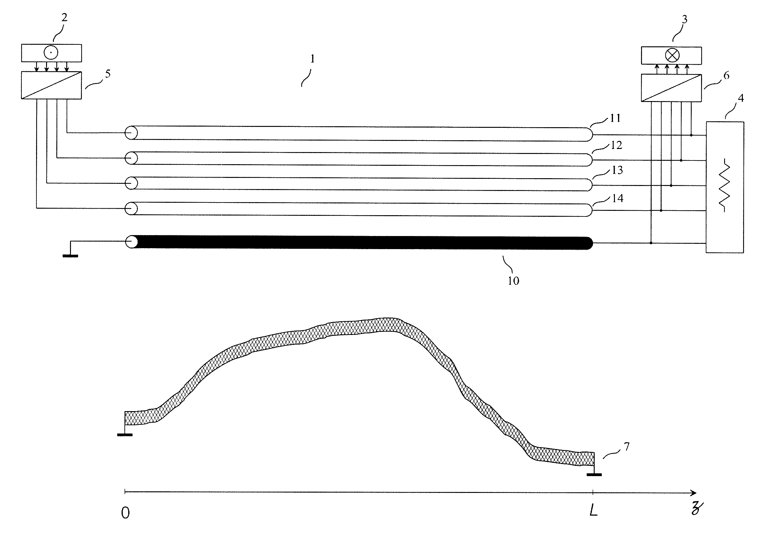
[0188]As a first embodiment of a device for implementing the method of the invention, given by way of non-limiting example, we have represented in FIG. 11 a device of the invention comprising an interconnection (1) built in a printed circuit board, the interconnection (1) having n=4 transmission conductors (11) (12) (13) (14) and a return conductor (10) distinct from the reference conductor (7). All items shown in FIG. 11 belong to the same printed circuit assembly and the reference conductor (7) is a ground plane of the printed circuit board of this printed circuit assembly. Said transmission conductors (11) (12) (13) (14) are traces built in the printed circuit board, above the reference conductor (7). A transmitting circuit (5) receives at its input the m=4 “input signals of the transmitting circuit” from the m channels of the source (2), and its n output terminals are connected to the transmission conductors (11) (12) (13) (14) of the interconnection (1), at the near-end of the ...

second embodiment (

Best Mode)

[0208]As a second embodiment of a device for implementing the method of the invention, given by way of non-limiting example and best mode of carrying out the invention, we have represented in FIG. 12 a device of the invention comprising an interconnection (1) having n=4 transmission conductors (11) (12) (13) (14) and a return conductor (10) distinct from the reference conductor (7). A transmitting circuit (5) receives at its input the m=4 “input signals of the transmitting circuit” from the m channels of the source (2), and its n+1 output terminals are connected to the conductors (10) (11) (12) (13) (14) of the interconnection (1), at the near-end of the interconnection (1). A termination circuit (4) is connected to the conductors (10) (11) (12) (13) (14) of the interconnection (1), at the far-end of the interconnection (1). A receiving circuit (6) has its n+1 input terminals connected to the conductors (10) (11) (12) (13) (14) of the interconnection (1), at the far-end of...

third embodiment

[0218]As a third embodiment of a device for implementing the method of the invention, given by way of non-limiting example, we have represented in FIG. 13 a device of the invention comprising an interconnection (1) built on the substrate of a multi-chip module (MCM), the interconnection (1) having n=3 transmission conductors (11) (12) (13) and a return conductor (10) distinct from the reference conductor (7). A transmitting circuit (5) receives at its input the m=3 “input signals of the transmitting circuit” from the m channels of the source (2), and its n output terminals are connected to the transmission conductors (11) (12) (13) of the interconnection (1), at the near-end of the interconnection (1). A termination circuit (4) is connected to the conductors (10) (11) (12) (13) of the interconnection (1), at the far-end of the interconnection (1). A receiving circuit (6) has its n+1 input terminals connected to the conductors (10) (11) (12) (13) of the interconnection (1), at the fa...


PUM


Abstract

The invention relates to a method and a device for pseudo-differential transmission in interconnections used for sending a plurality of electrical signals.The ends of an interconnection having 4 transmission conductors and a return conductor distinct from the reference conductor are each connected to a termination circuit. Three damping circuits are connected between the return conductor and the reference conductor. The transmitting circuits receive at their inputs the signals from the 4 channels of the two sources, and are connected to the conductors of the interconnection. A transmitting circuit in the activated state produces modal electrical variables, each modal electrical variable being allocated to one and only one channel. The receiving circuits are connected to the conductors of the interconnection, each receiving circuit being such that the 4 channels of a source connected to a transmitting circuit in the activated state are sent to the four channels of the destinations, without noticeable echo, internal crosstalk and external crosstalk.

Description

CROSS REFERENCE TO RELATED APPLICATIONS[0001]This is a Continuation Application of PCT application PCT / IB2009 / 052638, filed 19 Jun. 2009, published in English under No. WO 2010 / 015947, which in turn claims priority to French patent application number 08 / 04429 of 4 Aug. 2008, entitled “Procédé de transmission pseudo-différentiel utilisant des variables électriques modales”, both of which are incorporated herein by reference.FIELD OF THE INVENTION[0002]The invention relates to a method and a device for pseudo-differential transmission through interconnections used for sending a plurality of electrical signals, such as the interconnections made with multiconductor cables, or with the traces of a printed circuit board, or inside an integrated circuit.PRIOR ART[0003]Let us consider the problem of transmission through an interconnection, for obtaining m transmission channels, m being an integer greater than or equal to 2. Each transmission channel may be used for transmitting signals of a...

Claims


Application Information

Patent Timeline
Patent Type & Authority Patents(United States)
IPC IPC(8): H01P5/12
CPCH04B3/32H04L25/0272
Inventor BROYDE, FREDERICCLAVELIER, EVELYNE
Owner ZXNOISE LLC
Why Eureka
Try Eureka