Wind turbine comprising a generator cooling system

a cooling system and wind turbine technology, applied in the direction of electric generator control, machines/engines, mechanical equipment, etc., can solve the problems of loss, unfavorable cooling effect, and excessive moisture in the pod, so as to reduce the introduction of moisture and improve the cooling

Active Publication Date: 2011-11-08
WOBBEN ALOYS
View PDF22 Cites 23 Cited by
  • Summary
  • Abstract
  • Description
  • Claims
  • Application Information

AI Technical Summary

Benefits of technology

[0009]Therefore the object of the invention is to reduce the introduction of moisture, sand and other foreign substances into the pod as well as externally perceptible fan noises, and to permit more efficient cooling.

Problems solved by technology

In that respect, all situations involve the problem that losses occur, which also occur in the form of heat and which have to be dissipated.
That results in unwanted fouling of the pod, with the consequence of a faster rate of wear of components (just because of the abrasive effect of dust or sand) and a high level of air humidity in the pod, which is unwanted precisely when the weather is rainy, with all its adverse accompanying phenomena.

Method used


Image

  • Wind turbine comprising a generator cooling system
  • Wind turbine comprising a generator cooling system
  • Wind turbine comprising a generator cooling system

Examples


Embodiment Construction

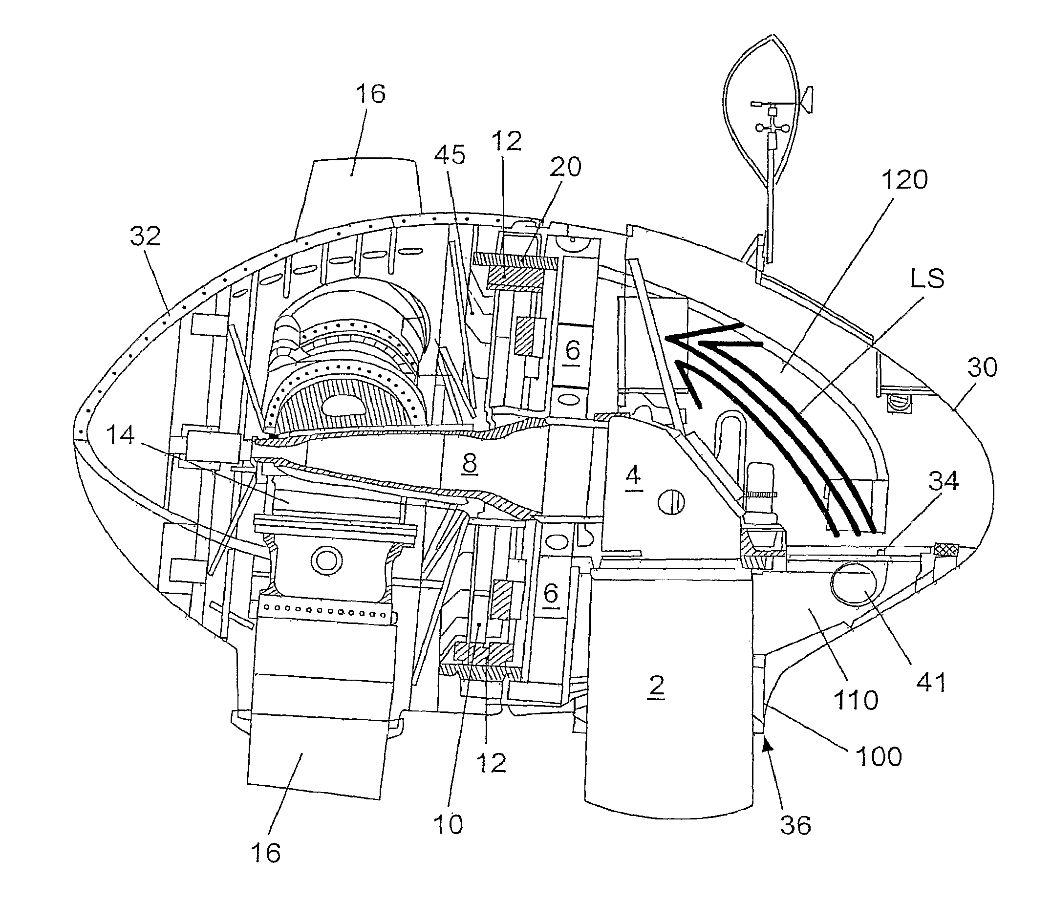
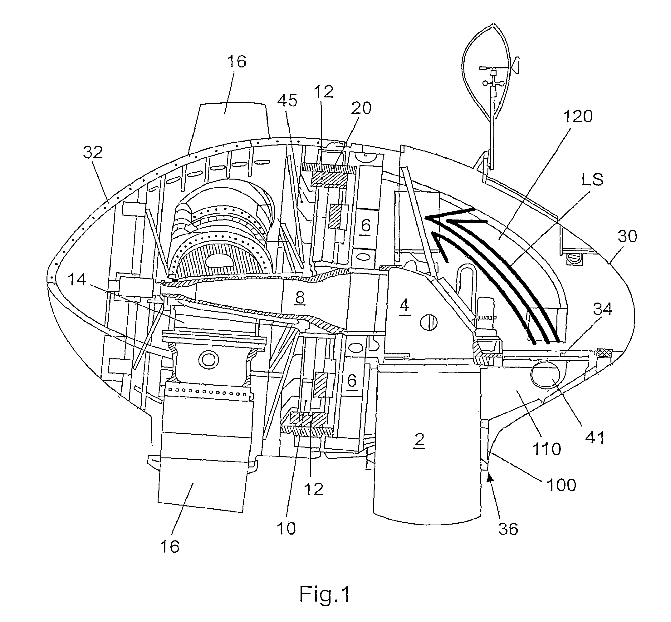
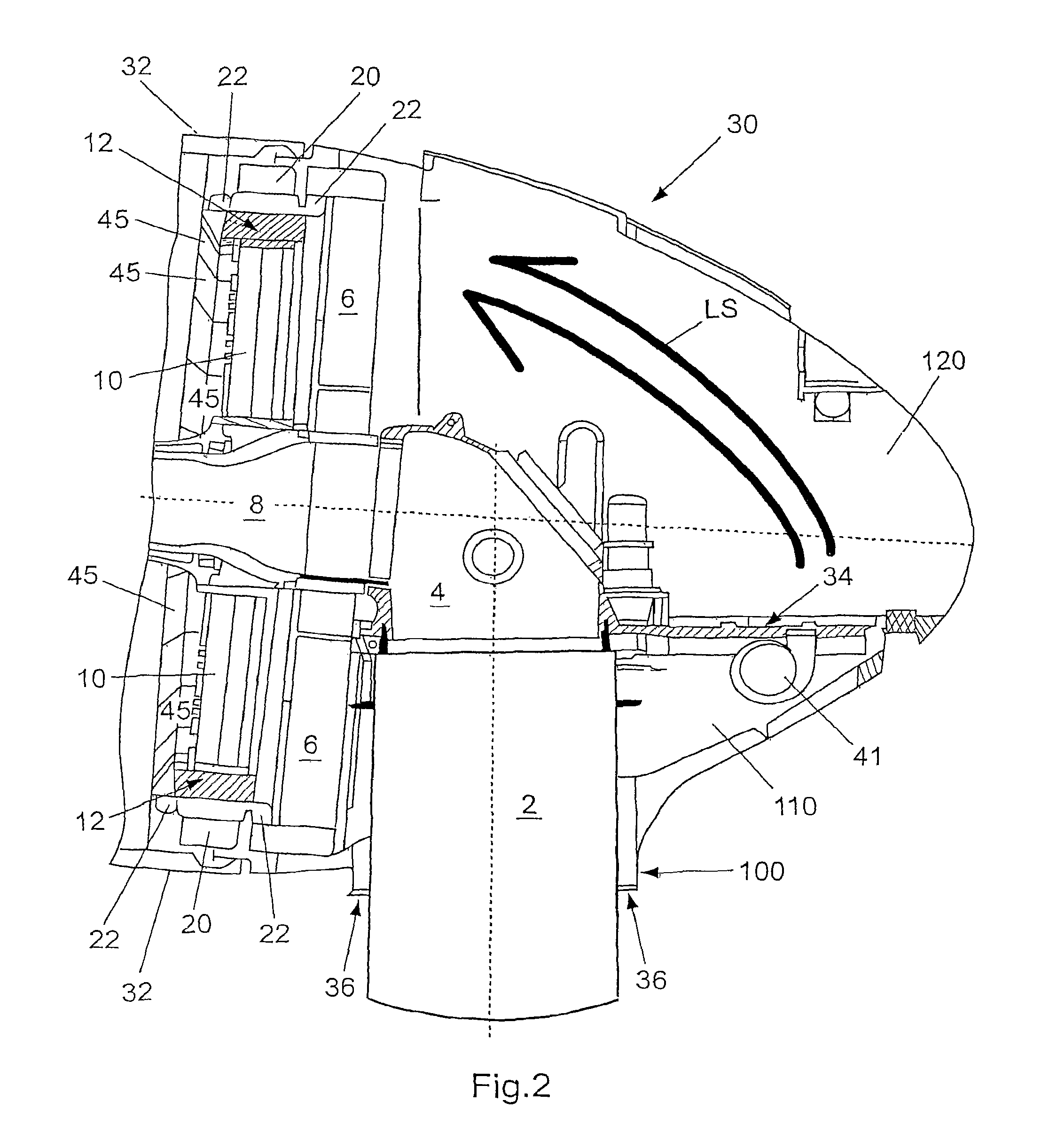
[0034]FIG. 1 shows a side view of a pod of a wind power installation according to the invention. In FIG. 1, shown on a pylon head 2 is a machine carrier 4 to which a stator carrier 6 and a journal 8 are in turn mounted. A hub 14 with the rotor blades 16 fixed thereto and a pole rotor 10 of the generator are arranged rotatably about the journal 8.

[0035]The stator 20 of the generator is carried by the stator carrier 6 while the pole rotor 10 (rotor) with pole windings and pole pieces 12 rotates within the generator together with the hub 14 on the journal 8. The structure on the pylon head 2 is enclosed by a pod 30, 32 which comprises a pod fairing 30 and a hub fairing 32. While the hub fairing 32 rotates with the hub 14 the pod fairing 30 encloses the stationary part of the pod. It will be appreciated in that respect that ‘stationary’ only denotes the rotary movement caused by the wind and transmitted by way of the rotor blades 16 to the hub 14 and the generator. In that respect wind ...


PUM


Abstract

A wind power installation is provided having a pylon, a pod mounted rotatably on the pylon, a generator arranged within the pod and having a rotor and a stator, and at least one fan in the region of the pod. In order to reduce the entry of moisture, sand and other foreign substances into the pod and also to reduce the fan noise which reaches the exterior, the fan may suck in outside air through a downwardly open first air gap, in particular between the pylon and the pod. The fan may be adapted to blow air out of a rear part of the pod, through an air gap between the stator and the rotor and into a front part of the pod. A seal structure may be positioned in the pod in such a way that an air flow that bypasses the air gap between the stator and the rotor is substantially prevented.

Description

BACKGROUND OF THE INVENTION[0001]1. Field of the Invention[0002]The present invention concerns a wind power installation comprising a pylon, a pod mounted rotatably on the pylon, a generator arranged within the pod and having a rotor and a stator, and at least one fan in the region of the pod.[0003]2. Description of the Related Art[0004]Such wind power installations have long been known in the state of the art. There is a large number of design configurations which operate in part with oil cooling, in part with air cooling or also with water cooling. In that respect, all situations involve the problem that losses occur, which also occur in the form of heat and which have to be dissipated. As each component has given thermal stress limits which must be observed, it is therefore necessary to provide adequate cooling in order to be able to dissipate the excess heat and avoid damage due to excessively raised temperatures.[0005]The invention is directed in particular to wind power instal...

Claims


Application Information

Patent Timeline
Patent Type & Authority Patents(United States)
IPC IPC(8): F03D9/00H02P9/04
CPCF03D9/002F03D11/00H02K9/04H02K7/1838F05B2220/7066F05B2260/20Y02E10/721Y02E10/722Y02E10/725Y02E10/726F03D9/25F03D80/60F03D80/50Y02E10/72
Inventor WOBBEN, ALOYS
Owner WOBBEN ALOYS
Why Eureka
Try Eureka