Spectral image processing method, computer-executable spectral image processing program, and spectral imaging system

a spectral imaging and processing method technology, applied in image enhancement, instruments, static indicating devices, etc., can solve the problems of insufficient noise reduction and worse accuracy of unmixing, and achieve high-performance spectral imaging and reduce noise

Active Publication Date: 2011-11-08
NIKON CORP
View PDF36 Cites 13 Cited by
  • Summary
  • Abstract
  • Description
  • Claims
  • Application Information

AI Technical Summary

Benefits of technology

[0015]According to the present invention, a spectral image processing method capable of reducing noise without damaging necessary information as much as possible and a

Problems solved by technology

However, measurement noise is superimposed on a spectral image being actual measurement data due to instability of a light source of a microscope, electric noise of a light detecting element of the microscope, and so on, which exerts a strong influence on the accuracy of unmixing.
In particular, when spectra of plural fluorescent reagents are similar, for example, when peak

Method used


Image

  • Spectral image processing method, computer-executable spectral image processing program, and spectral imaging system
  • Spectral image processing method, computer-executable spectral image processing program, and spectral imaging system
  • Spectral image processing method, computer-executable spectral image processing program, and spectral imaging system

Examples


Embodiment Construction

[0023]An embodiment of the present invention will be described. This embodiment is an embodiment of a spectral imaging fluorescent confocal laser microscope system.

[0024]First, the configuration of this system will be described.

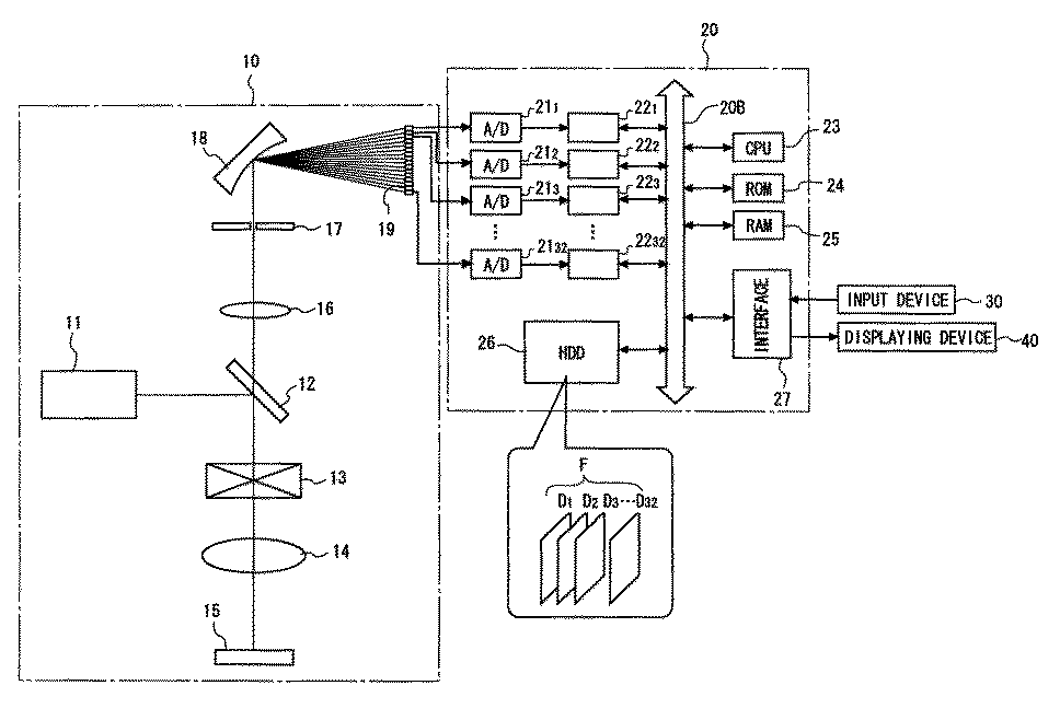
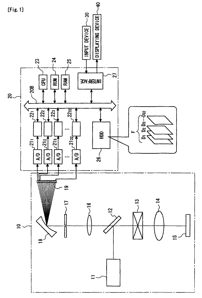
[0025]FIG. 1 is a configuration diagram of this system. As shown in FIG. 1, this system includes a main body of a microscope 10, a computer 20 connected thereto, and an input device 30 and a displaying device 40 connected thereto. The input device 30 is a mouse, a keyboard, and so on, and the displaying device 40 is an LCD or the like.

[0026]In the main body 10, a laser light source 11, a dichroic mirror 12, an optical scanner 13, an objective lens 14, a sample 15, an observation lens 16, a pinhole mask 17, a spectroscopic element 18, and a multichannel light detector 19 are placed. The sample 15 is labeled by plural types (for example, three types) of fluorescent reagents, and the multichannel light detector 19 has many (for example, 32) wavelength channels.

[...


PUM


Abstract

A spectral image processing method is capable of reducing noise while maintaining necessary information. The spectral image processing method performs processing on a spectral image of a specimen, including a step of normalizing spectra (=spectral brightness curves) of respective pixels constituting the spectral image such that their brightness levels become equal, a step of smoothing the normalized spectra in spatial directions of the respective pixels, and a step of denormalization of multiplying spectra of the respective pixels obtained by the smoothing by either one of brightness levels of the pixels corresponding the spectra and values corresponding to the brightness levels. Consequently, the noise can be reduced while information on brightness distribution on the image is maintained.

Description

CROSS-REFERENCE TO RELATED APPLICATION[0001]This application is a 371 of International Application Number PCT / JP2007 / 051698, filed Feb. 1, 2007, which claims the priority of Japanese Patent Application Number 2006-046508 filed Feb. 23, 2006.TECHNICAL HELD[0002]The present invention relates to a spectral image processing method of processing a spectral image acquired by a microscope or the like and a computer-executable spectral image processing program. Further, the present invention relates to a spectral imaging system such as a spectral-imaging fluorescent laser microscope.BACKGROUND ART[0003]In dynamic observation of an organism cell, a sample is labeled by a fluorescent material such as a fluorescent reagent or a fluorescent protein and observed by an optical microscope such as a fluorescent laser microscope in some cases. When plural fluorescent materials are used simultaneously, it is necessary to detect images of respective wavelength components (a spectral image).[0004]Howev...

Claims


Application Information

Patent Timeline
IPC IPC(8): G06K9/00
CPCG01N21/274G01N21/6458G06T5/10H04N1/409G06T5/002G06T5/20G06T5/50G06T2207/10056G06T2207/10064G06T2207/30024
Inventor OKUGAWA, HISASHIMIMURA, MASAFUMI
Owner NIKON CORP
Why Eureka
Try Eureka