Light-emitting module and illumination apparatus

a technology of light-emitting modules and illumination apparatuses, which is applied in the direction of lighting and heating apparatus, semiconductor devices for light sources, and light support devices. it can solve the problems of reducing the luminous efficacy of light-emitting diodes, preventing the achievement of sufficient optical output, and insufficient heat transfer to light-emitting diodes, so as to achieve sufficient optical output and suppress the increase in the temperature of light-emitting elements.

Inactive Publication Date: 2011-11-15
TOSHIBA LIGHTING & TECH CORP
View PDF34 Cites 55 Cited by
  • Summary
  • Abstract
  • Description
  • Claims
  • Application Information

AI Technical Summary

Benefits of technology

[0013]An object of the present invention is to obtain a light-emitting module capable of suppressing increase in temperature of a light-emitting element by emitting heat generated by a fluorescent material outside a translucent member, and achieving sufficient optical Output.
[0014]Another object of the present invention is to obtain an illumination apparatus capable of achieving sufficient brightness by mounting a light-emitting module having high luminous efficacy.

Problems solved by technology

The increase in temperature of the light-emitting diode chip causes decrease in luminous efficacy of the light-emitting diode chip, and sufficient optical output is prevented from being achieved.
According to the above-described configuration, since the fluorescent film is separated from the light-emitting diodes, even if heat is generated when light from the light-emitting diodes is wavelength-converted, the heat is not easily transferred to the light-emitting diodes.
In the above-described configuration, much of the heat generated by the fluorescent film during wavelength conversion is emitted only from the surface of the translucent panel, and the heat is easily trapped in the storing concave portion of the translucent panel.
Accordingly, the above-described configuration is susceptible to improvement regarding how to emit heat caused by wavelength conversion efficiently.

Method used


Image

  • Light-emitting module and illumination apparatus
  • Light-emitting module and illumination apparatus
  • Light-emitting module and illumination apparatus

Examples


first embodiment

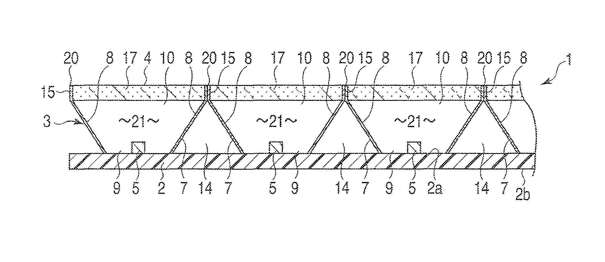
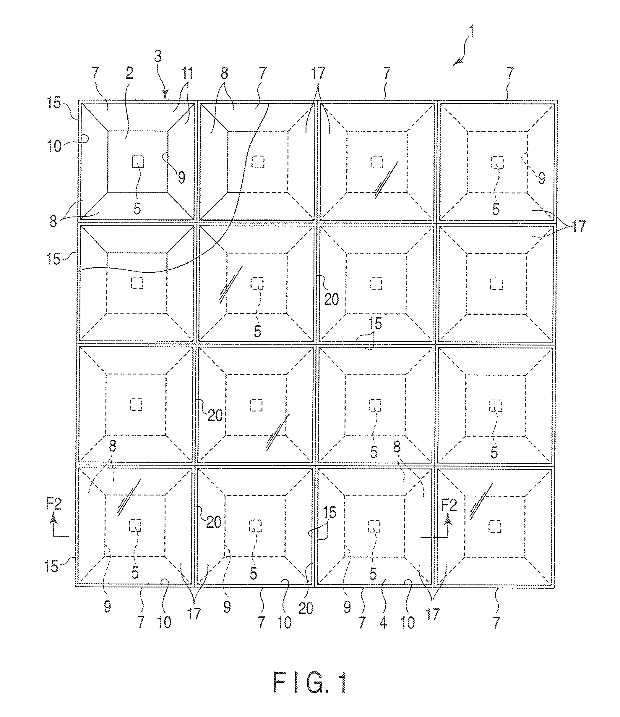
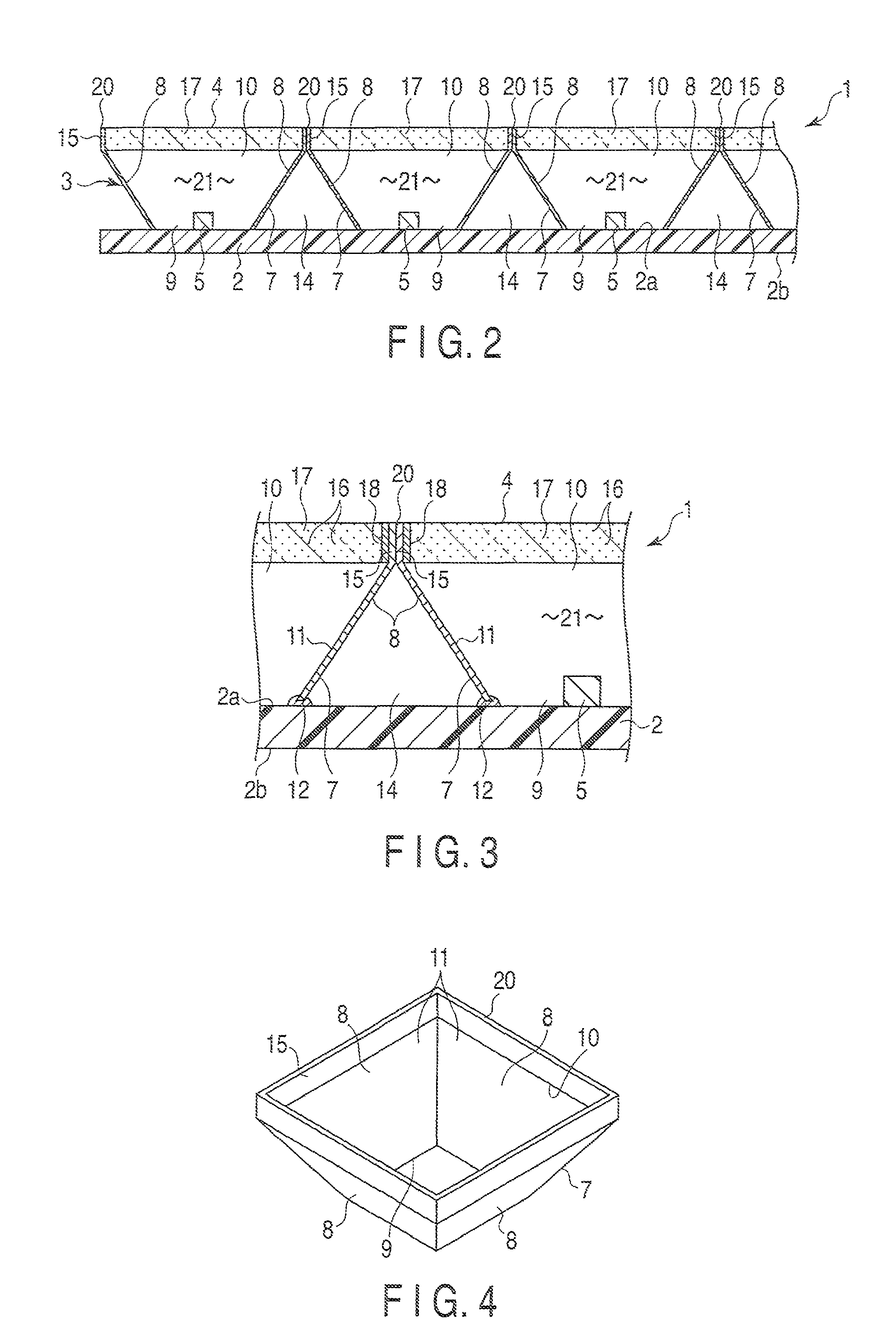
[0071]Hereinafter, a light-emitting module and an illumination apparatus according to the present invention will be described with reference to FIG. 1 to FIG. 6.

[0072]FIG. 1 and FIG. 2 disclose a light-emitting module 1. The light-emitting module 1 comprises a substratum 2, a frame 3 and a translucent member 4.

[0073]The substratum 2 is a plate having an approximately square shape, for example, and is formed of a flexible material, such as epoxy resin. The substratum 2 includes a flat mount surface 2a and a back surface 2b positioned on the opposite side of the mount surface 2a.

[0074]A plurality of light-emitting diode chips 5 are provided on the mount surface 2a of the substratum 2. The light-emitting diode chips 5, which are examples of light-emitting elements, are systematically arranged in a matrix on the mount surface 2a. Further, a wiring pattern, not shown, is formed on the mount surface 2a. The light-emitting diode chips 5 are arranged on the wiring pattern, and are connecte...

second embodiment

[0102]For example, FIG. 7 discloses a light bulb type LED lamp 41 according to the present invention. The LED lamp 41, which is an example of an illumination device, comprises an apparatus body 42, a light-emitting module 43, a lighting device 44, and a translucent cover 45. The apparatus body 42 has a semispherical shape including an opening 42a at one end. An E-type base 46 is attached to a top facing the opening 42a of the apparatus body 42.

[0103]The light-emitting module 43 is obtained by forming the light-emitting module 1 according to the first embodiment in a cylindrical shape, and has a basic configuration same as that of the light-emitting module 1. Accordingly, constituent elements same as those of the light-emitting module 1 will be denoted by the same reference numerals, and detailed descriptions of such elements will be omitted. One end of the cylindrical light-emitting module 43 is supported by the apparatus body 42. The light-emitting module 43 is arranged coaxially w...

fourth embodiment

[0114]In the fourth embodiment, a plurality of cell blocks 7 are integrally formed. Thereby, the frame 3 is formed as an integral structure, and the edges of peripheral walls 8 defining a second opening 10 of the cell blocks 7 are made continuous in a grid pattern.

[0115]The cell block 7 includes four heat conductors 62. The heat conductors 62 are integrally formed at the edges of the peripheral walls 8 defining the second opening 10 of the cell block 7. The heat conductors 62 protrude toward the opposite side of the substratum 2 from the edges of the peripheral walls 8, and are arranged at intervals in the peripheral direction of the second opening 10. The heat conductors 62 of adjacent cell blocks 7 are integrally formed.

[0116]Further, the tips of the heat conductors 62 form heat radiators 63 exposed to the outside of the translucent member 4. The heat radiators 63 are positioned on the same plane as the surface of the translucent member 4.


PUM


Abstract

A light-emitting module includes at least one light-emitting element provided on a mount surface of a substratum. A translucent member is provided so as to face the mount surface of the substratum. The translucent member is separated from the light-emitting element and contains a phosphor material that converts a wavelength of light emitted by the light-emitting element. A frame having heat conducting properties is interposed between the substratum and the translucent member. The frame surrounds the light-emitting element. The frame includes an opening that leads light emitted by the light-emitting element to the translucent member, and a heat conductor thermally connected to the translucent member. The heat conductor includes a heat radiator exposed outside of the translucent member.

Description

CROSS-REFERENCE TO RELATED APPLICATIONS[0001]This application is based upon and claims the benefit of priority from prior Japanese Patent Application No. 2008-316717, filed Dec. 12, 2008, the entire contents of which are incorporated herein by reference.BACKGROUND OF THE INVENTION[0002]1. Field of the Invention[0003]The present invention relates to a light-emitting module that uses a light-emitting diode chip, for example, as a light source, and more specifically to a structure for maintaining favorable luminous efficacy by suppressing increase in temperature of a light-emitting diode chip. The present invention further relates to an illumination apparatus on which the light-emitting module is mounted on the apparatus main body.[0004]2. Description of the Related Art[0005]For example, light-emitting diodes have higher efficiency and longer life spans than existing light sources such as fluorescent lamps and incandescent lamps. With improvement in luminous efficacy of light-emitting ...

Claims


Application Information

Patent Timeline
Patent Type & Authority Patents(United States)
IPC IPC(8): F21V3/00F21V9/40F21V29/505
CPCF21K9/00F21K9/135F21K9/56F21V9/16F21V29/502F21V29/004H01L2924/0002F21Y2101/02F21Y2111/005H01L25/0753H01L33/60H01L33/644F21V3/00H01L2924/00F21V13/14F21V29/70F21K9/232F21K9/64F21Y2107/30F21Y2115/10F21V3/08
Inventor TAKENAKA, ERIKAOGAWA, KOZOSHIMIZU, KEIICHIWATANABE, HIROAKITAKAHASHI, AKIMICHINOGI, SHINJIKUMASHIRO, SHINICHI
Owner TOSHIBA LIGHTING & TECH CORP
Why Eureka
Try Eureka