
Capacitively-coupled non-uniformly distributed amplifier

a capacitively coupled, non-uniform technology, applied in the direction of breathing filters, amplifiers with semiconductor devices/discharge tubes, breathing protection, etc., can solve the problems of limiting low frequency operation of das, reducing the linearity of da, etc., to broaden the output power bandwidth of capacitively-coupled nda, increase output impedance, and increase output impedance

Active Publication Date: 2011-11-15
QORVO US INC
View PDF12 Cites 7 Cited by
  • Summary
  • Abstract
  • Description
  • Claims
  • Application Information

AI Technical Summary

Benefits of technology

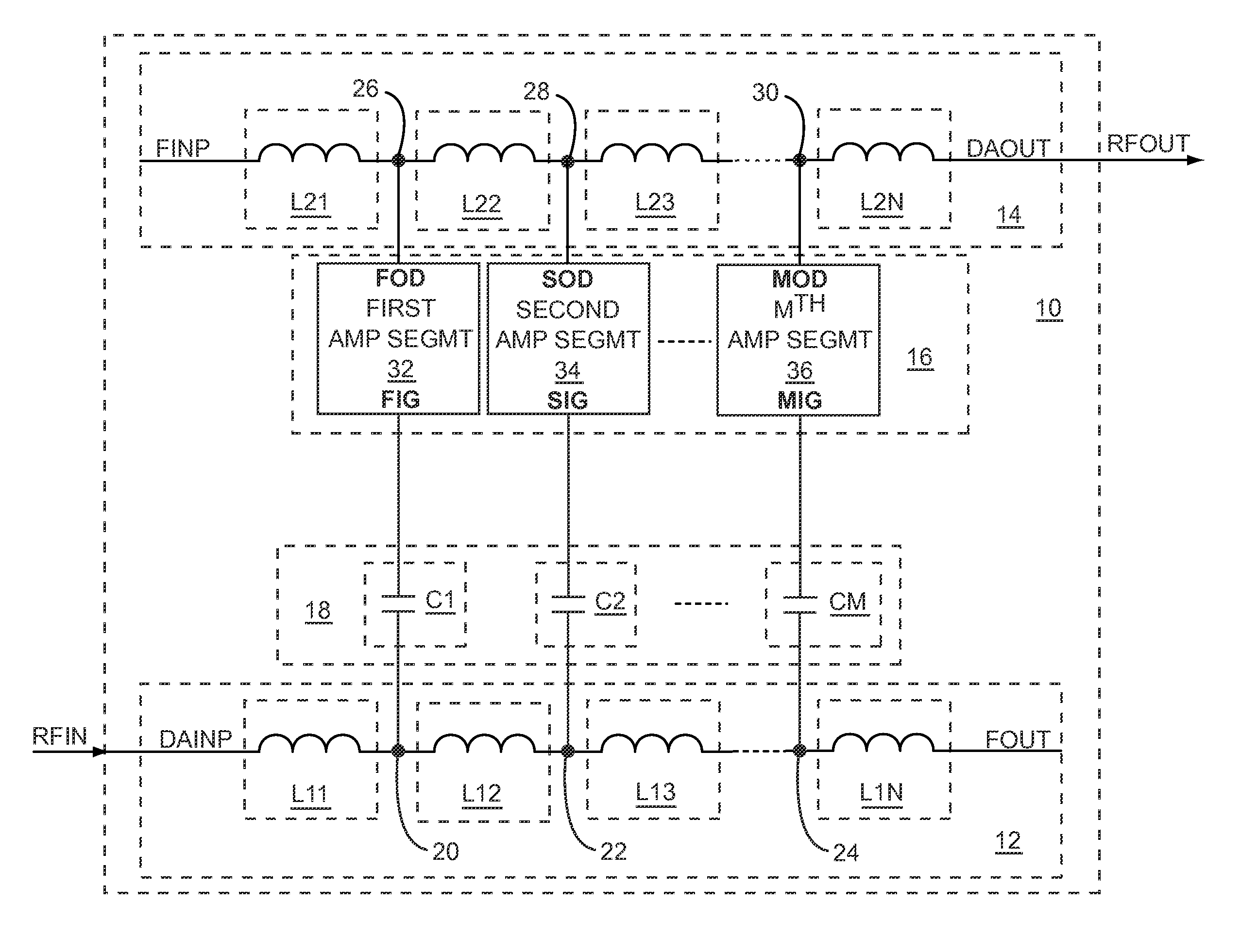
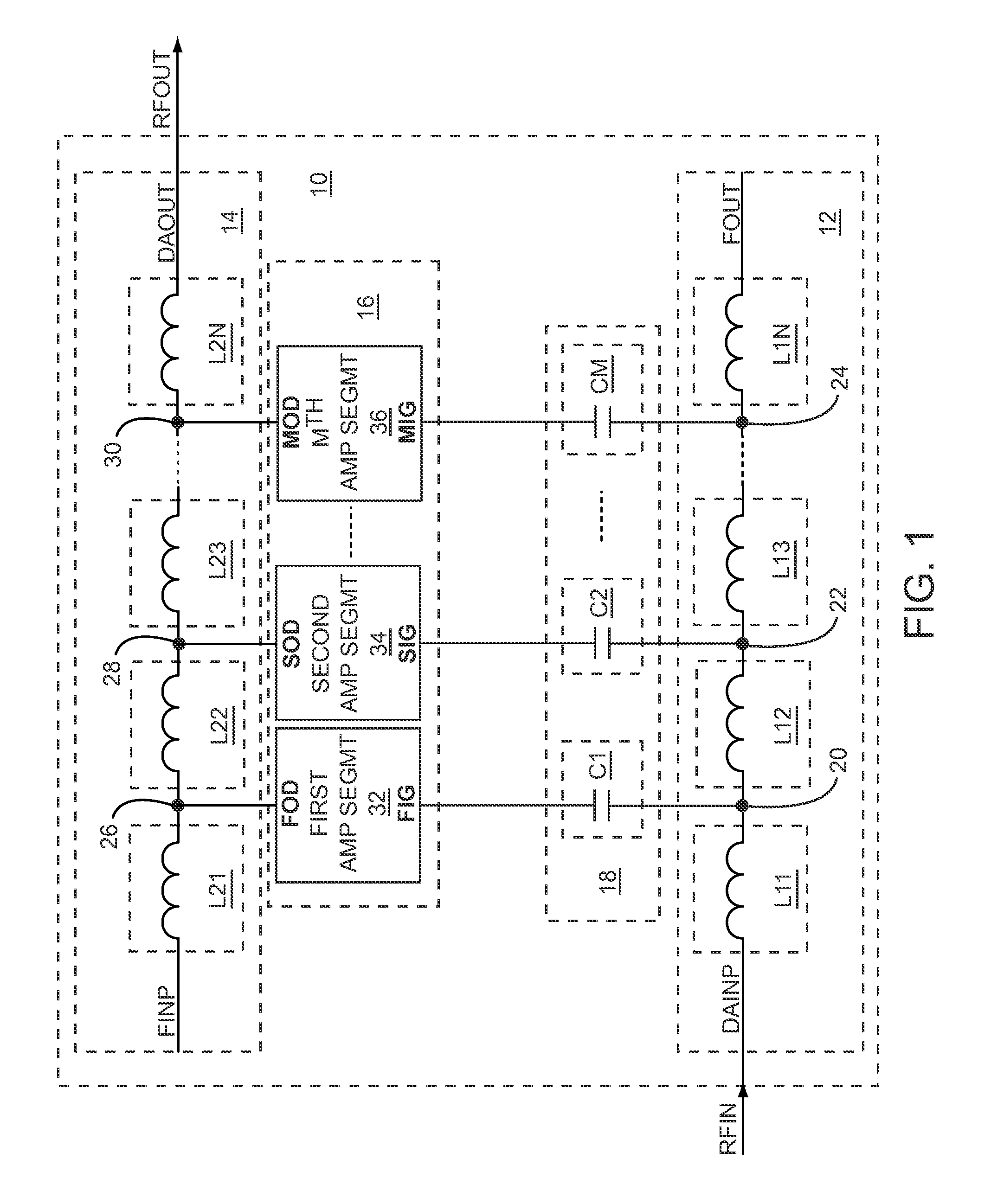
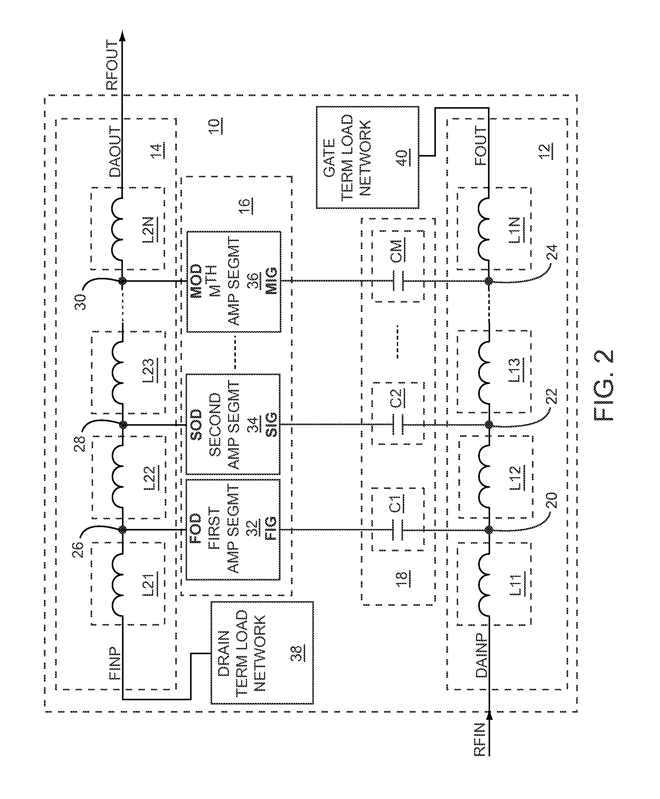
The present disclosure is about a capacitively-coupled non-uniformly distributed amplifier (NDA) that has an input line and an output line. The input line receives an input signal and the output line provides an output signal based on amplifying the input signal. The input network includes a group of capacitive elements coupled between the input line and the DA segments to extend a gain-bandwidth product of the NDA. The output line includes inductive elements, and since the NDA is non-uniformly distributed, an inductance of each inductive element decreases moving from an input end of the output line to an output end of the output line to compensate for decreasing impedance along the output line. The capacitively-coupled NDA may have phase velocity variations along the output line. To compensate for the phase velocity variations, a capacitance of each capacitive element that is coupled to the input line decreases moving from an input end of the input line to an output end of the input line. The decreasing capacitances associated with compensation for the phase velocity variations may cause uneven capacitive coupling to the DA segments. To correct for the uneven voltage division, tapered gate periphery transconductance devices may be used. The use of cascode DA segments, tapered gate periphery input and output transconductance devices, and adjusting a voltage division ratio of the resistor divider network may optimize the capacitively-coupled NDA. The use of tapered gate periphery output transconductance devices may increase the output power bandwidth of the capacitively-coupled NDA. The drain termination load network and the gate termination load network may provide partial impedance matches to the output line and the input line, respectively.

Problems solved by technology

However, practical DAs may have phase velocity variations, distortions, or both along the output line that may degrade the linearity of the DA, the efficiency of the DA, or both.
However, capacitive-coupling may limit low frequency operation of the DAs.

Method used


Image

  • Capacitively-coupled non-uniformly distributed amplifier
  • Capacitively-coupled non-uniformly distributed amplifier
  • Capacitively-coupled non-uniformly distributed amplifier

Examples


Embodiment Construction

[0007]The present disclosure relates to a capacitively-coupled non-uniformly distributed amplifier (NDA) having an input line and an output line that are coupled to one another through an input network and distributed amplifier (DA) segments. The input line receives an input signal and the output line provides an output signal based on amplifying the input signal. The input network includes a group of capacitive elements coupled between the input line and the DA segments to extend a gain-bandwidth product of the NDA. The output line includes inductive elements, and since the NDA is non-uniformly distributed, an inductance of each inductive element decreases moving from an input end of the output line to an output end of the output line to compensate for decreasing impedance along the output line. The capacitively-coupled NDA may have phase velocity variations along the output line. To compensate for the phase velocity variations, a capacitance of each capacitive element that is coup...


PUM


Abstract

The present disclosure relates to a capacitively-coupled non-uniformly distributed amplifier (NDA) having an input line and an output line that are coupled to one another through an input network and DA segments. The input network includes a group of capacitive elements coupled between the input line and the DA segments to extend a gain-bandwidth product of the NDA. The output line includes inductive elements, and since the NDA is non-uniformly distributed, an inductance of each inductive element decreases moving from an input end of the output line to an output end of the output line to compensate for decreasing impedance along the output line. To compensate for phase velocity variations along the output line, a capacitance of each capacitive element that is coupled to the input line decreases moving from an input end of the input line to an output end of the input line.

Description

RELATED APPLICATIONS[0001]This application is related to U.S. patent application Ser. No. 12 / 651,717, entitled CAPACITIVELY-COUPLED DISTRIBUTED AMPLIFIER WITH BASEBAND PERFORMANCE, filed on Jan. 4, 2010, which is concurrently filed herewith and is incorporated herein by reference in its entirety.[0002]This application claims the benefit of provisional patent application Ser. No. 61 / 142,283, filed Jan. 2, 2009, the disclosure of which is hereby incorporated herein by reference in its entirety.FIELD OF THE DISCLOSURE[0003]Embodiments of the present disclosure relate to distributed amplifiers, which may be used in radio frequency (RF) communications systems, optical fiber based communications systems, baseband frequency communications systems, or any combination thereof.BACKGROUND OF THE DISCLOSURE[0004]Several different amplifier applications require an amplifier having a large gain-bandwidth product. For example, RF signals on optical fibers may require large gain-bandwidth product a...

Claims


Application Information

Patent Timeline
Patent Type & Authority Patents(United States)
IPC IPC(8): H03F3/60
CPCA62B23/06
Inventor KOBAYASHI, KEVIN W.
Owner QORVO US INC
Learn More