Radiotherapeutic apparatus

a radiation therapy and apparatus technology, applied in the field of radiotherapy apparatus, can solve the problems of inability to treat the patient, inability to meet the patient's needs, and inability to meet the patient's needs, and achieve the effect of long aperture length and efficient radiation delivery

Active Publication Date: 2011-11-15
ELEKTA AB
View PDF20 Cites 31 Cited by
  • Summary
  • Abstract
  • Description
  • Claims
  • Application Information

AI Technical Summary

Benefits of technology

[0016]Helical tomotherapy offers a delivery efficiency that is exceptionally low. In order to achieve comparable plans, a 25 mm Fan Beam Thickness (FBT) is used, together with a Modulation factor (MF) of at least 3—lower values (higher efficiencies) lead to unacceptable plan quality. This results in 2 Gy dose delivery taking approximately 20 minutes beam on time. The dose rate of the beam source is approximately 10 Gy / min i.e. in 20 minutes the machine is capable of delivering 200 Gy. This means that the efficiency of dose delivery is about 1%. Typically using a conventional MLC, IMRT techniques offer an efficiency of about 500%. This means that to achieve the same leakage dose to the patient, the shielding of a tomotherapy machines needs to be 50 times as good. It also means that the machine consumes about 50 times as much electrical power to deliver each fraction, and generates 50 times as much heat. This may also limit the lifetime of other components.
[0018]The present invention seeks to provide a radiotherapeutic apparatus that mitigates the various problems found in the above techniques. It therefore provides a radiotherapeutic apparatus comprising a source of radiation whose output is collimated by a multi-leaf collimator, and a patient support, the source being rotatable around the support and the support being translatable along the axis of rotation, thereby to move the source helically relative to a patient on the support.
[0020]The apparatus thus moves the patient on the patient support system along the axis of rotation, in the longitudinal direction. Thus, the device has an effectively unlimited treatable volume in the longitudinal direction and avoids the limitations of IMAT and IMRT techniques. Despite this, thin MLC leaves can still be used to give a high longitudinal resolution.
[0021]A limited number of MLC leaves can be used, as the longitudinal motion extends the treatable length. This simplifies the engineering compared to a conventional MLC, where the number of leaves is required to be high enough to cover the treatable area. In this way, the use of thinner MLC leaves for higher resolution no longer implies a smaller treatment field.
[0023]Such a device offers a large number of treatment variables that can be optimised, thereby enabling similar or better dose distribution quality as compared to IMRT and IMAT. However, the long aperture length (compared to tomotherapy) makes the radiation delivery efficient and therefore the delivery of high doses a practicality; hypofractionation and radiosurgery therefore become possible over the large treatable volume that was previously only available via tomotherapy.

Problems solved by technology

There are distinct problems or limitations with all of the above techniques.
Thus, the treatable volume becomes limited.
In order to achieve comparable plans, a 25 mm Fan Beam Thickness (FBT) is used, together with a Modulation factor (MF) of at least 3—lower values (higher efficiencies) lead to unacceptable plan quality.
This results in 2 Gy dose delivery taking approximately 20 minutes beam on time.
It also means that the machine consumes about 50 times as much electrical power to deliver each fraction, and generates 50 times as much heat.
This may also limit the lifetime of other components.
This also means that hypofractionation techniques are not practicable in the context of helical tomotherapy.

Method used


Image

  • Radiotherapeutic apparatus
  • Radiotherapeutic apparatus

Examples


Embodiment Construction

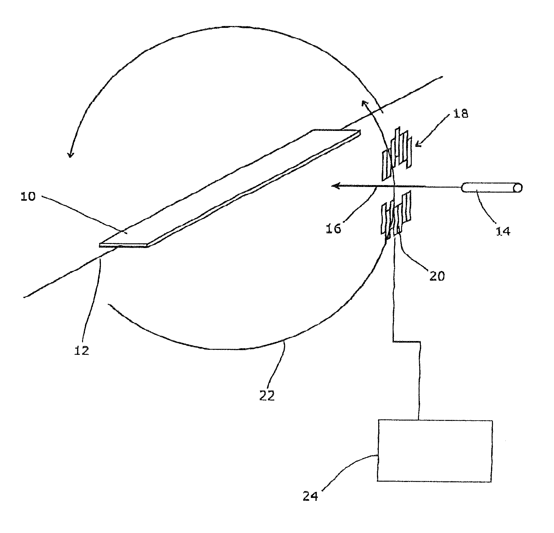
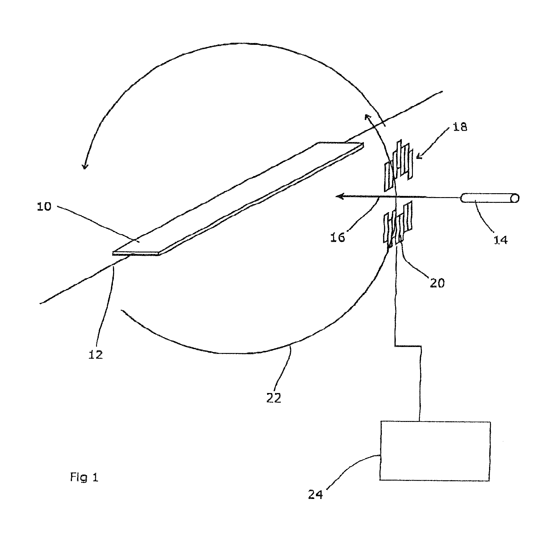
[0026]FIG. 1 shows, in outline, the apparatus used by the present invention. A patient support 10 is provided that is moveable along a longitudinal axis 12. A source of radiation 14 is also provided, on a mount (not shown) that allows it to be rotated around the longitudinal axis 12. Thus, the longitudinal axis of the patient support and the rotational axis of the radiation source are aligned. The source is directed towards the axis 12, such that its beam 16 intersects with the axis.

[0027]A multi-leaf collimator (MLC) 18 is provided for the radiation source 14. The leaves 20 of the MLC are oriented perpendicular to the beam 16 and to the axis 12. Accordingly, the leaves are in line with the tangential direction of the source 14 along its rotary path. This therefore collimates the radiation beam from a cone to what can be considered as a plurality of fan beams whose included angle is continuously variable. A computational means 24 is also provided for calculating leaf positions for t...


PUM


Abstract

The present invention seeks to provide a radiotherapeutic apparatus that mitigates the various problems found in the techniques such as tomotherapy, IMAT, IMRT and the like. It provides a radiotherapeutic apparatus comprising a source of radiation whose output is collimated by a multi-leaf collimator, and a patient support, the source being rotatable around the support and the support being translatable along the axis of rotation, thereby to move the source helically relative to a patient on the support. The leaves of the MLC are preferably oriented orthogonal to the axis of rotation, to simplify computation of the dose distribution. The apparatus thus moves the patient on the patient support system along the axis of rotation, in the longitudinal direction. Thus, the device has an effectively unlimited treatable volume in the longitudinal direction and avoids the limitations of IMAT and IMRT techniques whilst enabling the use of thin MLC leaves to give a high longitudinal resolution. The apparatus is preferably combined with an optimization system providing a computational service similar to that provided for IMAT and IMRT devices. Essentially the same computational techniques could be used, with appropriate changes to the input conditions and characteristic equations. The long aperture length (compared to tomotherapy) makes the radiation delivery efficient and therefore the delivery of high doses a practicality; hypofractionation and radiosurgery therefore become possible over large treatable volumes.

Description

RELATED APPLICATIONS[0001]This application is a 35 U.S.C. 371 national stage filing of International Application No. PCT / GB2006 / 000725, filed 1 Mar. 2006, which claims priority to Great Britain Patent Application No. 0504897.0 filed on 10 Mar. 2005 in Great Britain. The contents of the aforementioned applications are hereby incorporated by reference.FIELD OF THE INVENTION[0002]The present invention relates to a radiotherapeutic apparatus.BACKGROUND ART[0003]It is known that exposure of human or animal tissue to ionising radiation will kill the cells thus exposed. This finds application in the treatment of pathological cells. In order to treat tumours deep within the body of the patient, the radiation must however penetrate the healthy tissue in order to irradiate and destroy the pathological cells. In conventional radiation therapy, large volumes of healthy tissue can thus be exposed to harmful doses of radiation, resulting in prolonged recovery periods for the patient. It is, there...

Claims


Application Information

Patent Timeline
Patent Type & Authority Patents(United States)
IPC IPC(8): A61N5/10G21K1/04
CPCA61N5/1042A61N5/1047A61N5/01G21K1/04
Inventor BROWN, KEVIN
Owner ELEKTA AB
Why Eureka
Try Eureka