Method and system for extending life of a vehicle energy storage device

a technology for energy storage devices and vehicles, applied in the direction of battery/fuel cell control arrangement, secondary cell servicing/maintenance, hybrid vehicles, etc., can solve the problems of affecting the operating life and performance characteristics of such devices, affecting the operating life and storage capacity of an energy storage device, and frequent cycles of periodic charging and discharging of energy storage devices

Inactive Publication Date: 2011-11-22
GENERAL ELECTRIC CO
View PDF24 Cites 81 Cited by
  • Summary
  • Abstract
  • Description
  • Claims
  • Application Information

AI Technical Summary

Benefits of technology

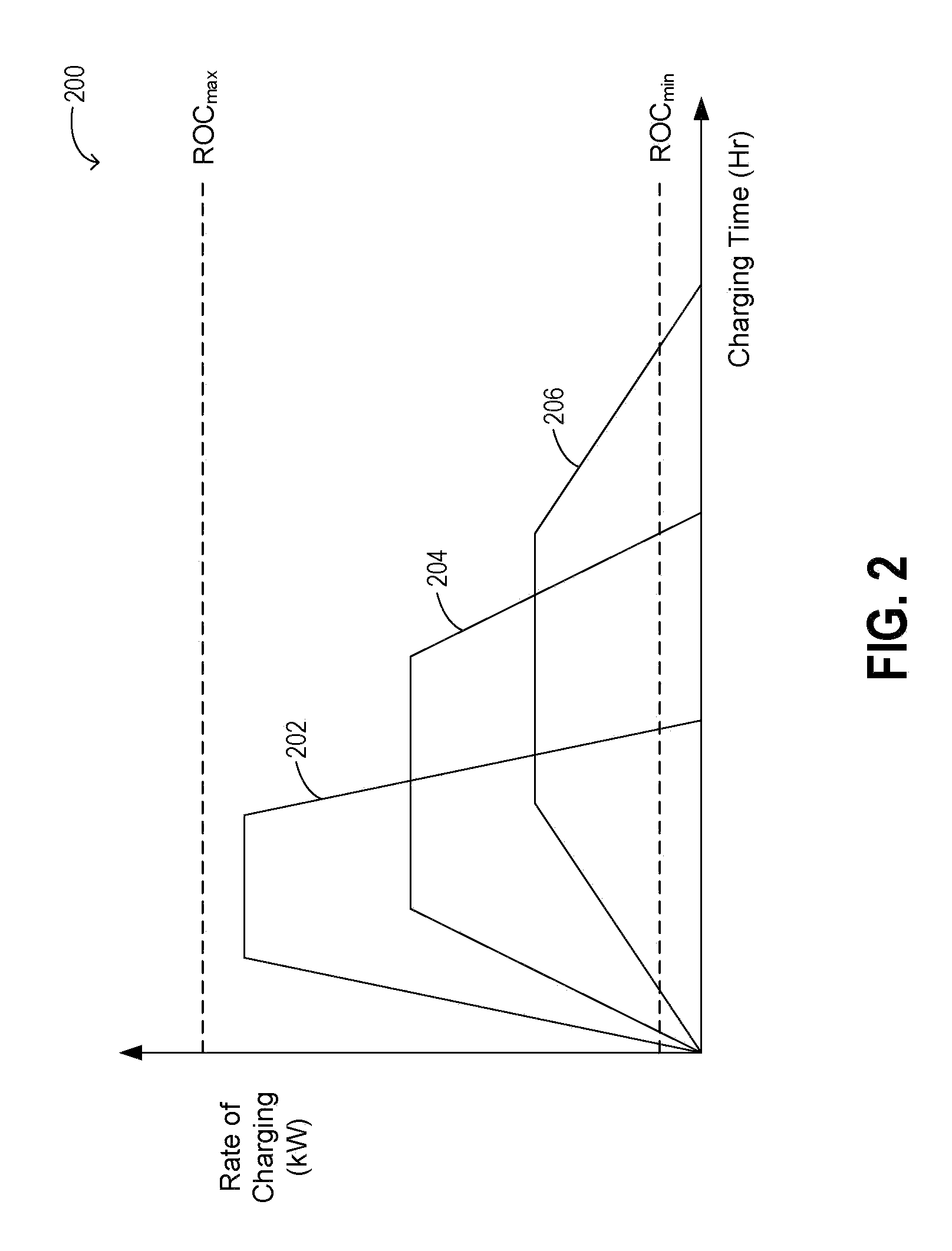
[0005]In one example, it may be predetermined that an upcoming power transfer opportunity is a long duration charging opportunity. Accordingly, the power transfer rate for the upcoming charging opportunity may be assigned a value below a maximum allowed charging rate. Additionally, the energy storage device may be discharged to a lower initial state of charge in the preceding discharging opportunity. In this way, the energy storage device may be completely charged, albeit at a slower rate, by the end of the long duration charging opportunity, but not earlier. In another example, it may be predetermined that an upcoming power transfer opportunity is a short duration charging opportunity. Accordingly, the power transfer rate for the upcoming charging opportunity may be assigned a higher, or even maximal value. Additionally, the energy storage device may be discharged to a higher state of charge in the preceding discharging opportunity. Consequently, the energy storage device may be completely charged, albeit at a faster rate, by the end of the shorter duration charging opportunity, but not earlier. In this way, it is possible to take advantage of a priori information about future charging and discharging opportunities (e.g., information known, deduced, and / or estimated before a future charging or discharging opportunity) to better utilize longer charging durations through a lower charging rate and through prior discharging to a lower initial state of charge. Such operation not only provides a more efficient power transfer, but also reduces degradation of the energy storage device in the vehicle, while still reaching the desired state of charge at the conclusion of the opportunity.
[0006]With a priori information regarding the plurality of future charging and discharging opportunities, and durations thereof, in a given vehicle mission, it may be further possible to customize the power transfer profile for each future power transfer opportunity. In one example, by adjusting the power transfer rate in to and / or out of an energy storage device to affect a current state of charge and by adjusting the power transfer rate based on an estimated duration of a future power transfer opportunity, over-charging and under-charging may be avoided, thereby extending the life of the device. Additionally, in another example, by breaking a bulk power transfer event of the energy storage device into smaller power transfer opportunities, and by further adjusting the power transfer profile during each of those upcoming opportunities based on an operating condition of the energy storage device, such as a device age, temperature, capacity, etc, the life of the device may be extended and the performance optimized. Additionally, in another example, by breaking the power transfer event into separate voltage and current demands based on an operating condition of the energy storage device, such as a device age, temperature, capacity, state of charge, and the like, the life of the device may be extended and the performance optimized.

Problems solved by technology

During operation, the energy storage devices experience frequent cycles of periodic charging and discharging.
Further, the operating life and performance characteristics of such devices can be affected by the rate and depth of charging / discharging and / or the current level at which charging / discharging occurs.
Use of faster and deeper rates and higher current levels during charging / discharging events adversely affect the operating life and storage capacity of an energy storage device.
The age of the device, frequency of usage, and temperature of storage are some additional parameters affecting its performance.
Reduced performance of electrical energy storage devices in turn may affect the performance and fuel efficiency of the electric vehicle (or hybrid electric vehicle) in which they are used.

Method used


Image

  • Method and system for extending life of a vehicle energy storage device
  • Method and system for extending life of a vehicle energy storage device
  • Method and system for extending life of a vehicle energy storage device

Examples


Embodiment Construction

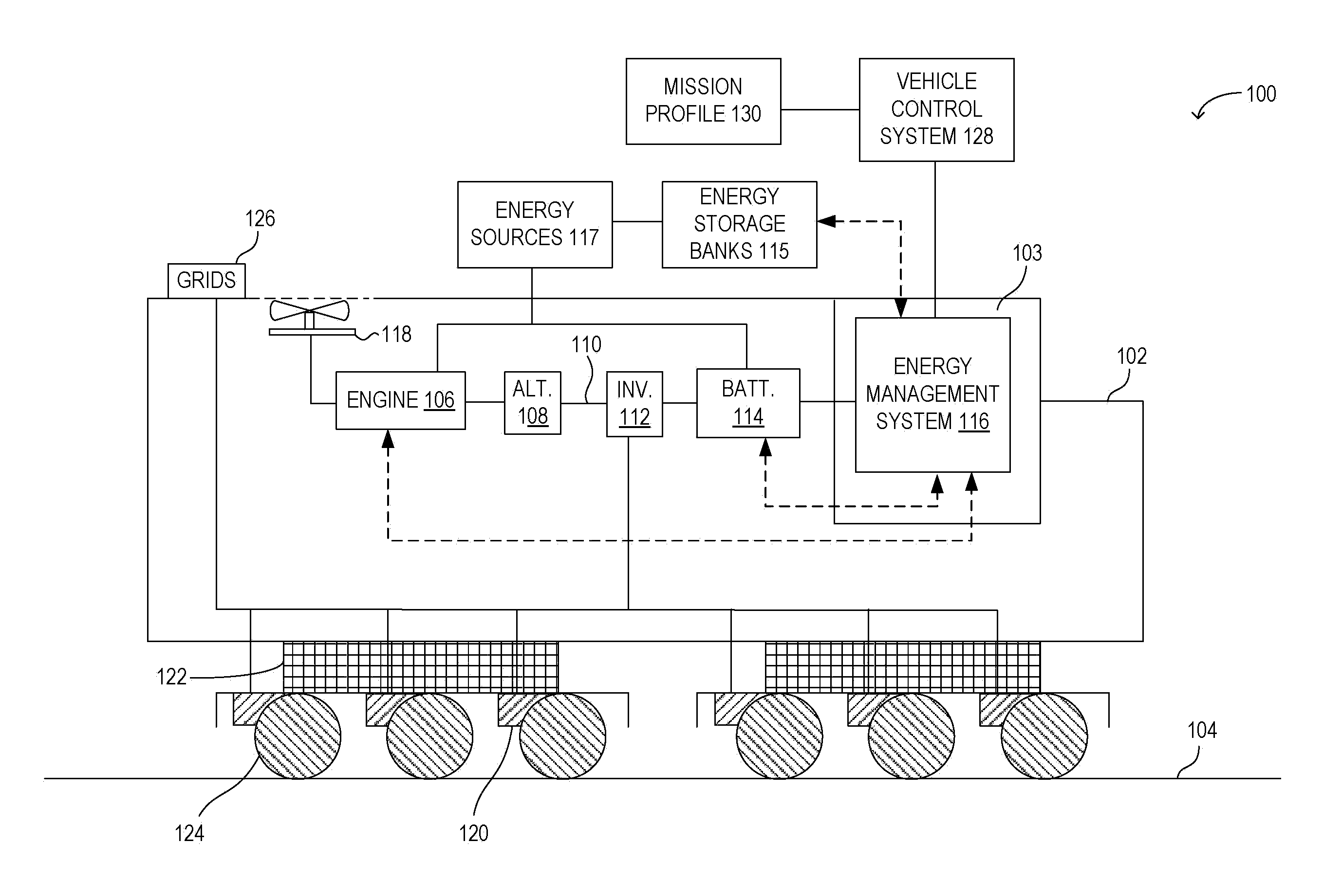
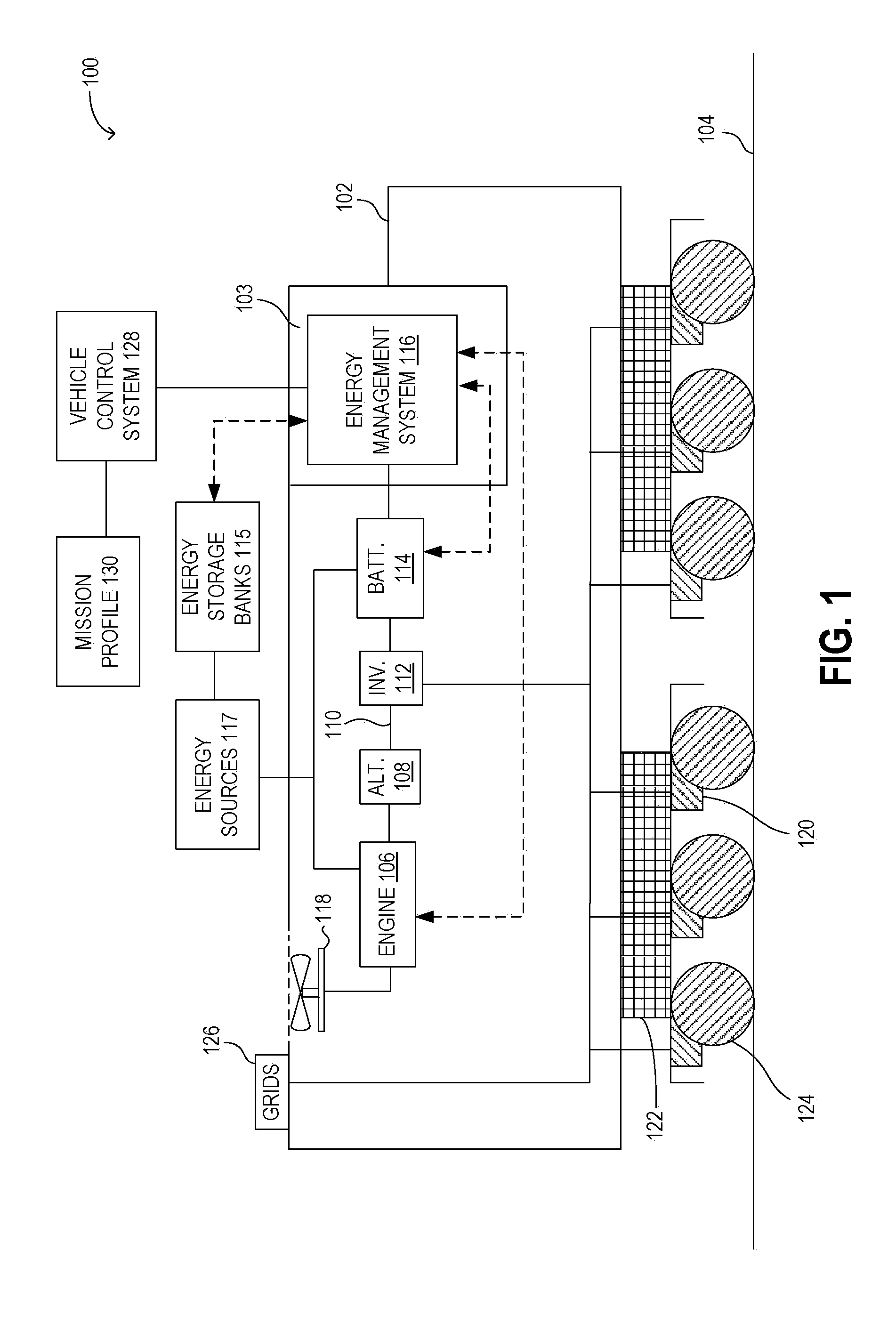
[0015]Vehicles, such as locomotives operating with rechargeable electrical energy storage devices, may be configured with integrated energy management systems that control power transfer profiles to and from the energy storage device. The power transfer profile may be controlled based not only on the operating condition of the energy storage device, but also responsive to charging / discharging opportunities available during a mission and other inherent characteristics of the device that may affect the device's performance. One example is illustrated with reference to FIG. 1 wherein an energy management system monitors the operating conditions of a locomotive's on-board electrical energy storage device and accordingly adjusts the charging / discharging profile so as to maximize the operating life of the device. The charging cycle of the energy storage device may be optimized into a plurality of sub-charging cycles that match the expected performance and life of the device.

[0016]As illus...


PUM


Abstract

Methods and systems are provided for controlling a power transfer rate in to and / or out of a vehicle energy storage device to affect a current state of charge of the energy storage device. The vehicle may be on a mission comprising a plurality of future power transfer opportunities. In one example, the method comprises adjusting the power transfer rate based on an estimated duration of a future power transfer opportunity. Further, the method may include, if the estimated duration of the future power transfer opportunity is different from a predetermined threshold, changing the power transfer rate at the future power transfer opportunity. The method allows the operating life of the energy storage device to be extended.

Description

FIELD[0001]The subject matter disclosed herein relates to a method and system for improving the performance of a vehicle energy storage device to thereby extend the operating life of the device.BACKGROUND[0002]Electric and hybrid electric vehicles, such as locomotives, operate with on-board rechargeable electrical energy storage devices. The energy storage devices may include one or more types of batteries, super-capacitors, utracapacitors, and flywheel systems.[0003]During operation, the energy storage devices experience frequent cycles of periodic charging and discharging. Further, the operating life and performance characteristics of such devices can be affected by the rate and depth of charging / discharging and / or the current level at which charging / discharging occurs. Use of faster and deeper rates and higher current levels during charging / discharging events adversely affect the operating life and storage capacity of an energy storage device. The age of the device, frequency of ...

Claims


Application Information

Patent Timeline
Patent Type & Authority Patents(United States)
IPC IPC(8): H02J7/00B60L50/15
CPCB60L3/0046B60L7/06B60L11/123B60L11/1861B60L11/1864B60L11/1874H01M10/44B60L3/0092B60L2200/26Y02T10/6217Y02T10/7005Y02T10/7044Y02T10/7061Y02T10/7077Y02T10/7258B60L50/61B60L58/14B60L58/15B60L58/18B60L58/21B60L58/26Y02E60/10Y02T10/62Y02T10/70Y02T10/72Y02T10/7072
Inventor SALASOO, LEMBITKING, ROBERT DEANIACOVANGELO, CHARLESDAUM, WOLFGANG
Owner GENERAL ELECTRIC CO
Why Eureka
Try Eureka