Eureka AIR delivers breakthrough ideas for toughest innovation challenges, trusted by R&D personnel around the world.

Liquid cooling and dispensing device

a liquid cooling and dispensing device technology, applied in the direction of liquid transferring devices, domestic cooling devices, lighting and heating devices, etc., can solve the problems of no means to control the final temperature of wine, system is however bulky, loss of taste and enjoyment, etc., to increase the retention time, increase the cooling of liquid, and stable flow of liquid

Inactive Publication Date: 2011-11-29
RAVI SOLUTION INC (CA)
View PDF18 Cites 10 Cited by
  • Summary
  • Abstract
  • Description
  • Claims
  • Application Information

AI Technical Summary

Benefits of technology

[0010]Accordingly, a primary object of the present invention is to provide a liquid cooling and dispensing device which can cool a liquid.
[0012]Another object of the present invention is to provide a liquid cooling and dispensing device which can control the flow of the liquid.
[0018]The liquid cooling and dispensing device of the present invention further comprises a vent tube which is adapted to extend inside the bottle. The vent tube is further in fluid communication with a vent opening located on the side of the enclosure or on the side of the base. The vent tube and the vent opening allow air to enter the bottle as the liquid is poured therefrom. The vent tube and the vent opening therefore equilibrate the internal pressure of the bottle to allow a stable flow of the liquid when the latter is poured.
[0019]According to one aspect of the present invention, the vent opening can be closed, for instance, via the thumb or any other finger of the user, to stop the flow of the liquid inside the conduit or conduits and therefore increase the cooling of the liquid by increasing the retention time. Upon removal of the thumb, the liquid would flow again.
[0020]According to another aspect of the present invention, the flow control element of the spout can be adjusted to increase or decrease the flow of the liquid upon pouring. By diminishing the flow rate, the retention of the liquid inside the conduit (or conduits) is increased. By increasing the retention time, the contacting time between the liquid in the conduit (or conduits) and the cooling material is also increased, effectively augmenting the cooling of the liquid. Conversely, if the flow rate is increased, the retention time of the liquid inside the conduit (or conduits) is decreased, with a corresponding diminution of the cooling effect. The flow control element of the spout therefore allows the user to adjust the cooling effect of the device to obtain a beverage cooled according to its preferred serving temperature.

Problems solved by technology

Thus, a bottle of wine which is just out of the cellar and at the perfect temperature will unfortunately reach room temperature if left to its own device, with all the lost in taste and enjoyment.
Though these devices can effectively cool a bottle of wine, there is no means to control the final temperature of the wine and the latter generally becomes ice cold.
This system is however bulky and the wine which remains in the coil between two servings will generally become ice cold, which is generally not wanted, particularly for red wines.
As for the device of Terziau et al., the chiller of Rist is bulky and is not adapted for all types of glasses.
The problem with the cooler of Busch is that there is no way to control the flow of the liquid.
Furthermore, there is no venting means to equilibrate the pressure inside the bottle as the liquid is poured, resulting in an unstable flow.

Method used


Image

  • Liquid cooling and dispensing device
  • Liquid cooling and dispensing device
  • Liquid cooling and dispensing device

Examples


first embodiment

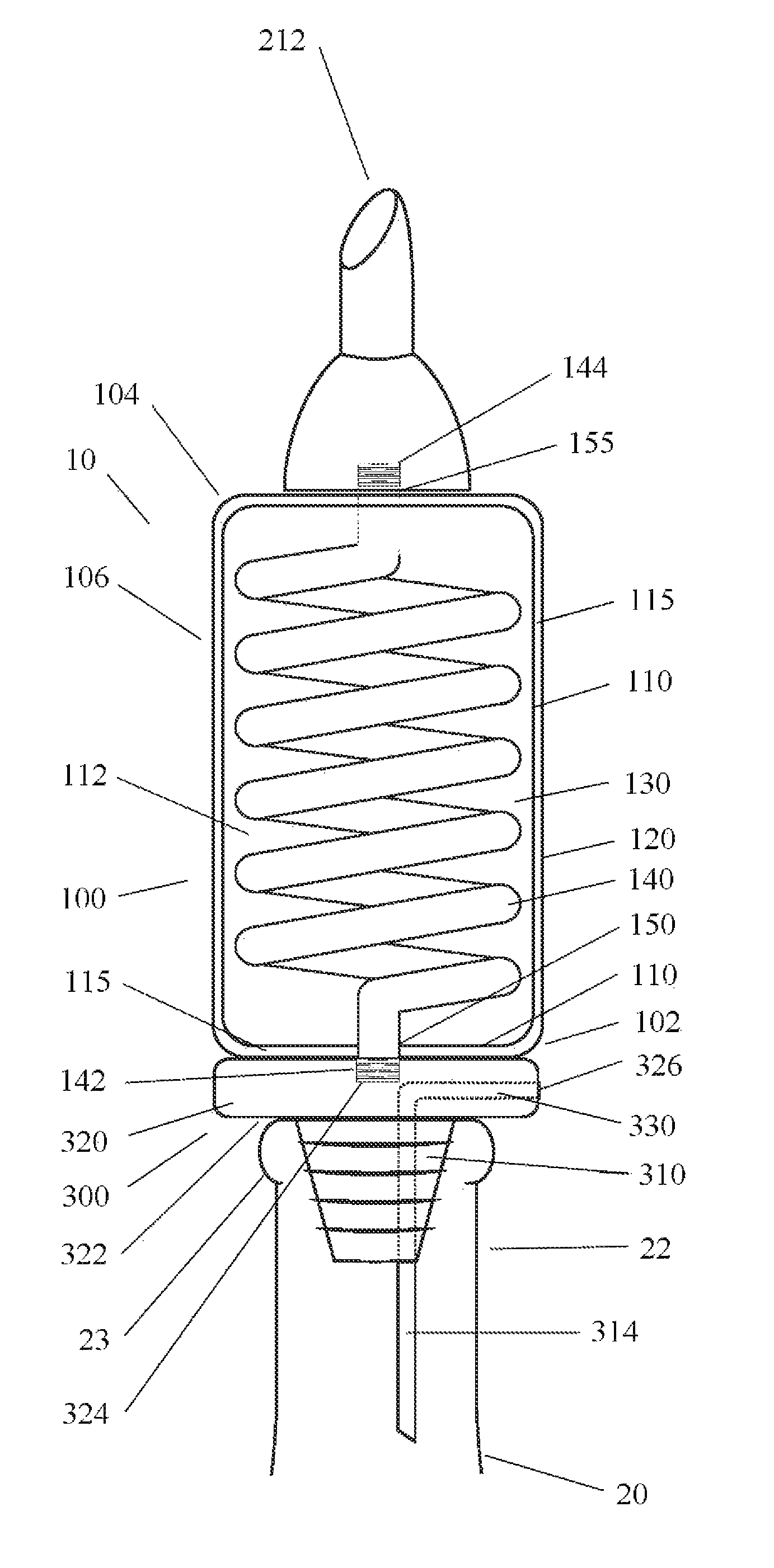
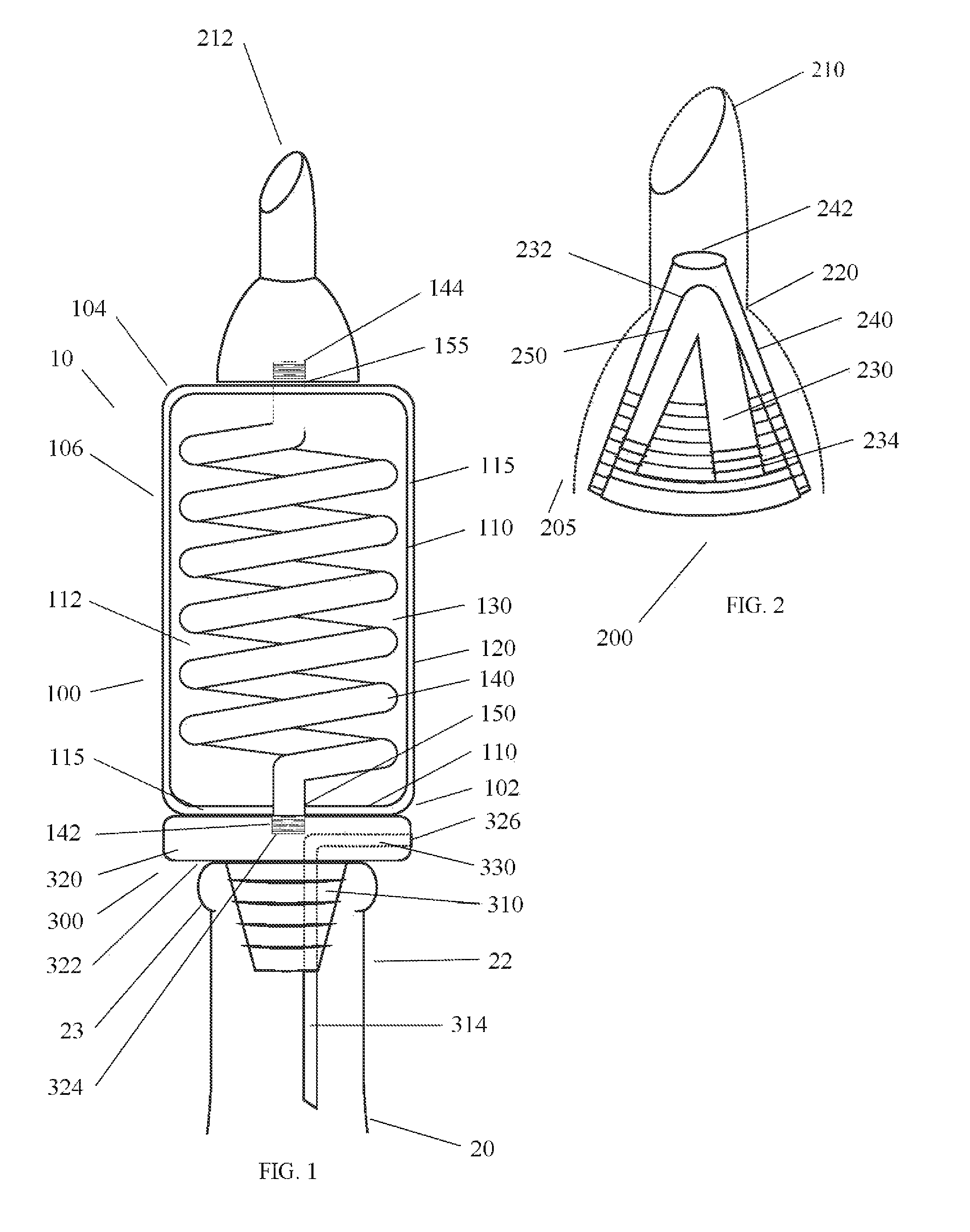
[0038]Referring first to FIG. 1, we can see the liquid cooling and dispensing device 10 of the present invention. As described above, the device 10 is generally used to cool a liquid contained in a bottle 20 as the liquid is poured therefrom. As per the invention, the device 10 is preferably designed to be directly mounted to the neck 22 of a bottle 20 (partially shown in FIG. 1).

[0039]In the first embodiment, the device 10 generally comprises three main components, an enclosure 100 to which are mounted a spout 200 and a base 300. The spout 200 and the base 300 are preferably removable in order to ease the cleaning of the device 10.

[0040]The enclosure 100 of the device 10 generally comprises an inner wall 110 and an outer wall 120 which define a space 115 therebetween. The inner wall 110 defines an inner chamber 112 which is filled with cooling material 130. For the purpose of the invention, any cooling material having a freezing point preferably lower than 0 degree Celsius can be u...

second embodiment

[0065]Referring now to FIGS. 5 to 12, the liquid cooling device of the present is disclosed.

[0066]Referring first to FIGS. 5 and 6, the second embodiment 510 of the liquid cooling device generally comprises an enclosure 600 and a base or bottleneck adapter 800 mounted to the bottom portion 602 thereof.

[0067]Referring now more particularly to FIG. 7, the enclosure 600 of the second embodiment 510 generally comprises an outer wall 620 and an inner wall 610 which define a space 615 therebetween. The inner wall 610 further defines an inner chamber 612 inside of which extends a preferably metallic tubular coil 640 through which will flow the liquid to be cooled. Understandably, there could be more than one coils 640 and / or the coil 640 could be made of other heat conductive material, the present invention is not so limited.

[0068]According to the present invention, in order to cool the liquid as it flows through the coil 640, the inner chamber 612 is further filled with low freezing mater...


PUM


Abstract

A device that attaches to a bottle's neck has a base that secures to the bottle's neck and has two passages that traverse the base. The first passage leads to an enclosure located above the base that holds cooling material and optionally has a conduit that improves the heat exchange between a dispensing liquid and the cooling material retained in the enclosure. The exit passage of the enclosure has in at least one embodiment a valve. The second passage through the base forms a vent line that is located entirely below the enclosure and allows air to flow into the bottle as bottle's contents are dispensed through the first passage.

Description

CROSS-REFERENCE TO RELATED APPLICATIONS[0001]The present patent application claims the benefits of priority of commonly assigned Canadian Patent Application No. 2,540,426, filed on Mar. 20, 2006, at the Canadian Intellectual Property Office and entitled: “Liquid Cooling and Dispensing Device”.FIELD OF THE INVENTION[0002]The present invention generally relates to liquid cooling devices and apparatuses for cooling potable liquid. More particularly, the present invention relates to bottle-mounted liquid cooling devices and apparatuses.BACKGROUND OF THE INVENTION[0003]It is generally well known that all drinks and beverages are not drunk at the same temperature. Whereas some drinks like soft drinks are generally drunk cold or even ice-cold, some other drinks like tea or coffee are drunk hot. In any case, when a particular drink or beverage is left at room temperature, it will itself eventually reach that same room temperature.[0004]In the case of wines, this is generally to be avoided s...

Claims


Application Information

Patent Timeline
Patent Type & Authority Patents(United States)
IPC IPC(8): B67D7/80
CPCF25D3/08F25D2303/0831F25D2331/803F25D2331/811F25D2600/04F25D2700/16
Inventor TETREAULT, MARTINJODOIN, JEAN-FRANCOIS
Owner RAVI SOLUTION INC (CA)
Why Eureka
Eureka Blog
Learn More