[0014]The present invention seeks to provide a viewing
system that is capable of rendering a scene at infinity focus, whilst simultaneously offering motion
parallax and autostereoscopic views by combining an infinity display (based on a light guide) with a lenticular array (a plurality of cylindrical lenses or “lenticules”), the advantages of the combined technologies overcoming the inherent drawbacks of each. The
forging of these two technologies results in an overall superior display, the collimating
optics of the light guide can be more compact, while the orthogonal
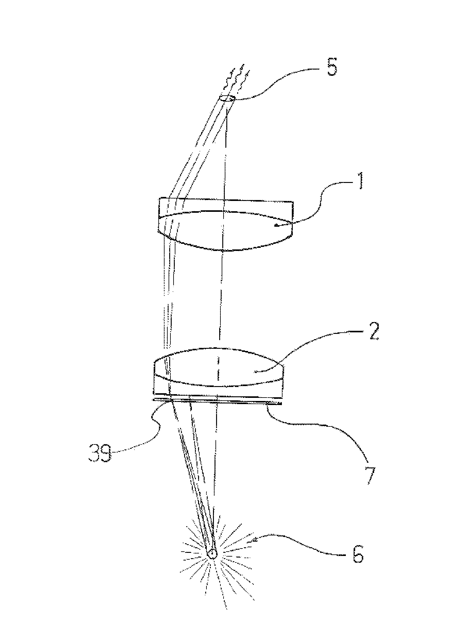
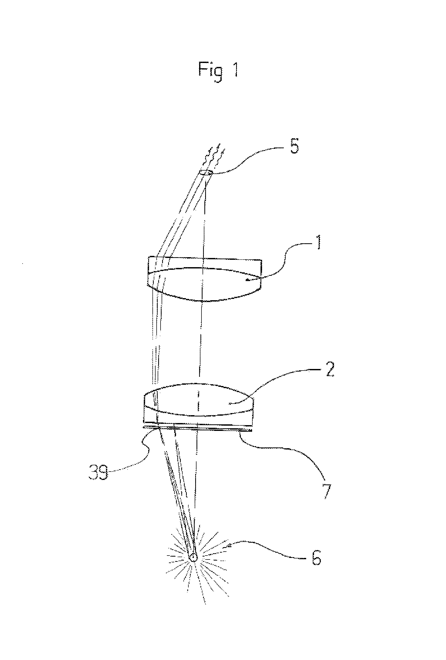
distortion that besets deep-view lenticular autostereoscopes (brought on by the astigmatic properties of their cylindrical lenslets), disappears. Indeed, by combining features of an infinity display with a lenticular array, the present invention offers what is effectively a high quality auto stereoscopic infinity display. However, although auto stereoscopic viewing of near range objects is possible (with some compromises), the device is designed to preferentially display uncompromised mid to distant autostereoscopic views. Note; the above mentioned lenticular array serves two purposes in that it (a) collimates light in the horizontal plane as required by the infinity display and (b) affords motion
parallax in the horizontal plane by bringing to infinity focus multiple, juxtaposed images, (one beneath each lenticule), as is usual for lenticular displays.
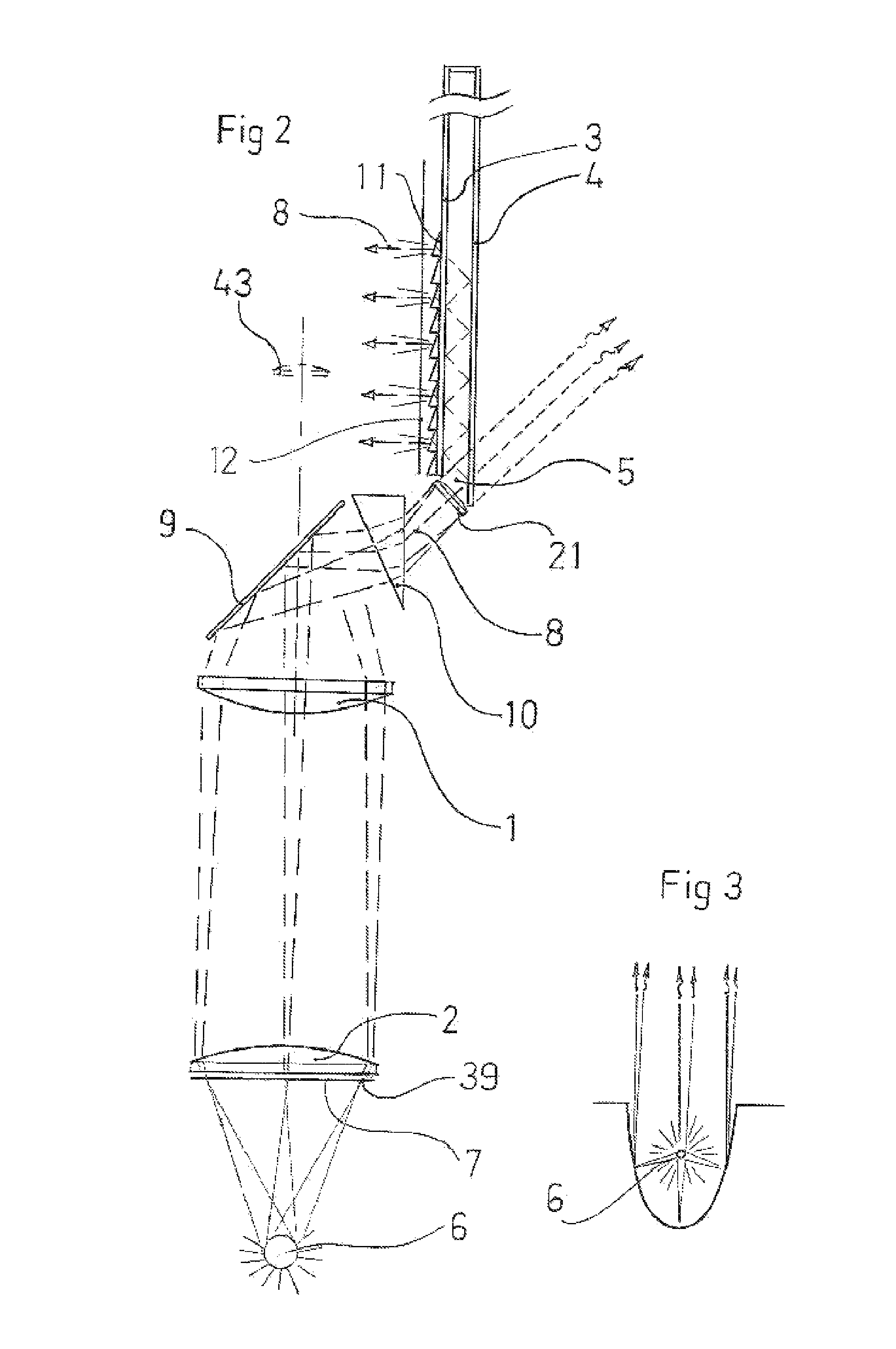
[0020]Preferably, said light guide has first surfaces of two mirrors, at least one of which is partially transmissive or; said light guide has two partially transmissive first surfaces allowing displayed images to be viewed from both sides of the present invention or; said light guide is composed of first surfaces on a flat sheet of transparent media such as glass, where at least one of the first surfaces is partially transmissive. The optical component for collimating horizontal rays (that have been modulated by an SLM), consists of a plurality of cylindrical astigmatic lenses such as are found in a lenticular display or; a single
linear array of stigmatic lenses if we wish to simultaneously collimate both the vertical and horizontal rays. In one embodiment, a refractive
prism would be used to spectrally disperse said rays prior to them entering the light guide's
entrance pupil so that a “
ray straightening” optical conjugate of said
prism such as a Fresnel
prism can reinstate the earlier relationship between the modulated rays
spectral properties and their geometry in accordance with Snell's law, as they exit the display. Alternatively, we can separate the one image into three, displayed on the SLM as displaced red, green and blue images, and then inject them into the light guide without them passing through a refractive prism, thereby allowing the
ray straightening
optics to both straighten and merge the rays to produce the one, coherent image.
Parallax can be improved by sweeping the horizontally collimated rays of spatially modulated light, (the degree of sweep commensurate with the
pitch of the lenticular array or
linear array of stigmatic lenses if the latter are employed), by rapidly moving said array back and forth in two or more discrete steps with each step being accompanied by a change in perspective of the
associated image formed by the SLM. Alternatively, the horizontally collimated rays, mentioned above, are rapidly oscillated by a wedged shape prism in respect to an identical, conjugated static prism. The breadth of field and
image resolution in the horizontal plane can also be improved using a lenticular micro-
lens array in conjunction with a lenticular
macro-
lens array such that the lenticular micro-
lens array directs three different images into three corresponding lenses of the
macro array, using prior art principles of lenticular micro-lens arrays.

