Lamination shaping apparatus

a technology of lamination and shaping apparatus, which is applied in the direction of butter manufacturing, manufacturing environment conditioning, glue vessels, etc., can solve the problems of inability to precisely fabricate objects of the order of micrometers, and the accuracy of the object being formed in the prior art is affected, so as to achieve easy fabrication, eliminate the factor of degrading the accuracy of the object being formed, and the effect of high precision

Active Publication Date: 2011-12-06
MATSUSHITA ELECTRIC WORKS LTD
View PDF19 Cites 37 Cited by
  • Summary
  • Abstract
  • Description
  • Claims
  • Application Information

AI Technical Summary

Benefits of technology

[0030]The present invention enables to stack the powder layers (cured layers) on the base while keeping the base stationary, thus eliminating a factor of degrading the accuracy of the object being formed on the base and therefore assuring easy fabrication of highly precise lamination object. In a version in which the milling unit is employed to grind the surface of a precursor of the laminated object between the repeated steps of preparing the powder layer and the curing it into the cured layer, it is possible to avoid possible fluctuation of the laminated object at the time of grinding, thereby also assuring easy fabrication of highly precise lamination object.

Problems solved by technology

However, the above prior art sees a drawback as to accuracy of the laminated object.
However, since the shaping stage 61 carrying thereon the object is made movable, the precursor of the object is likely to suffer from a minute positional fluctuation during the course of irradiating the light beam to sinter or melt for solidification, or using a milling machine for grinding, which makes it difficult to precisely fabricate the object having the order of micrometers.

Method used


Image

  • Lamination shaping apparatus
  • Lamination shaping apparatus
  • Lamination shaping apparatus

Examples


Embodiment Construction

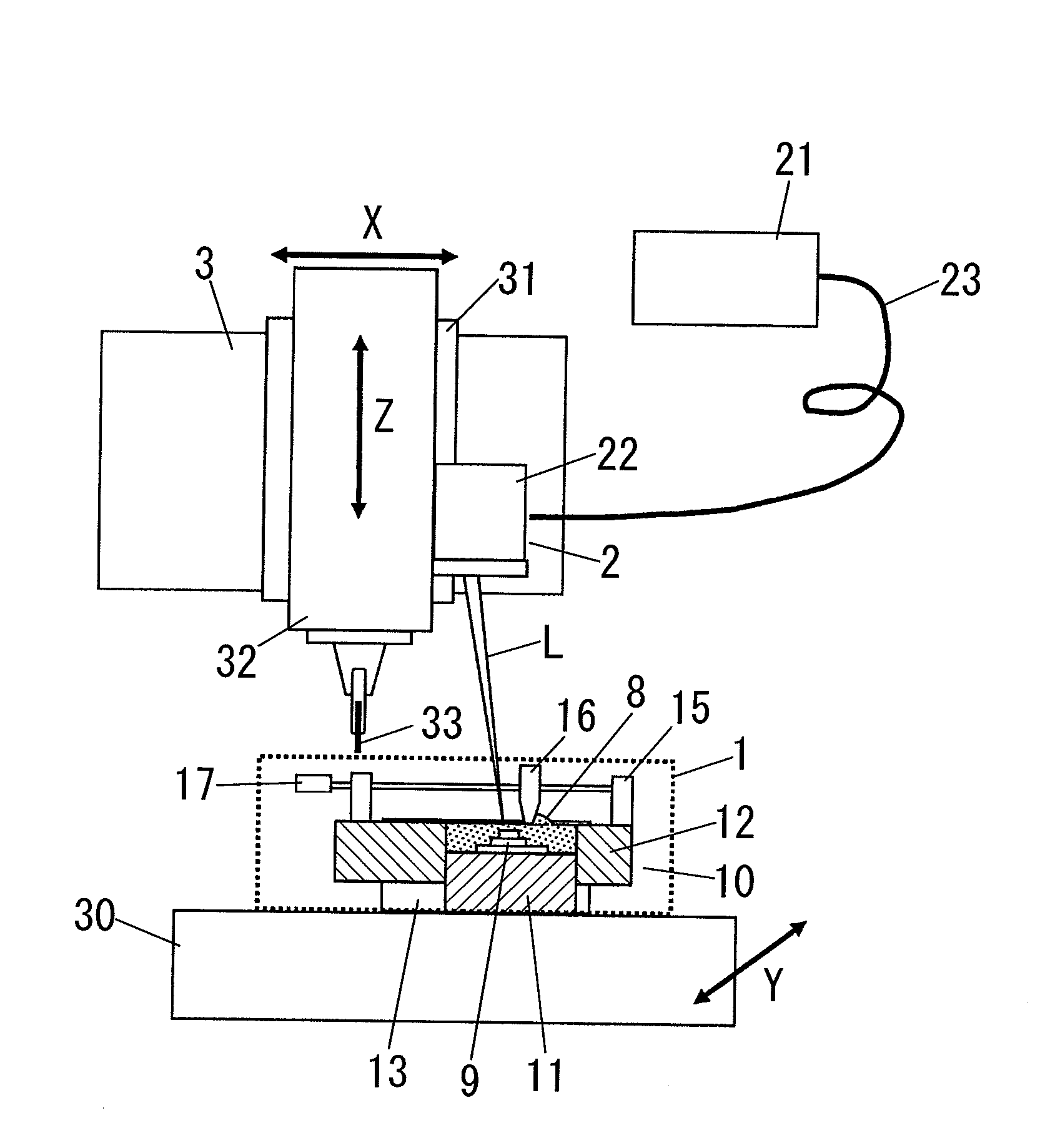
[0063]The present invention is now explained with reference to the attached drawings. FIG. 1 illustrates a lamination shaping apparatus which includes a shaping unit 1 composed of a shaping section 10 and a powder supply section 15 disposed on the shaping section 10, an optical unit 2 irradiating a light beam L to the shaping section 10, and a milling unit 3 for grinding.

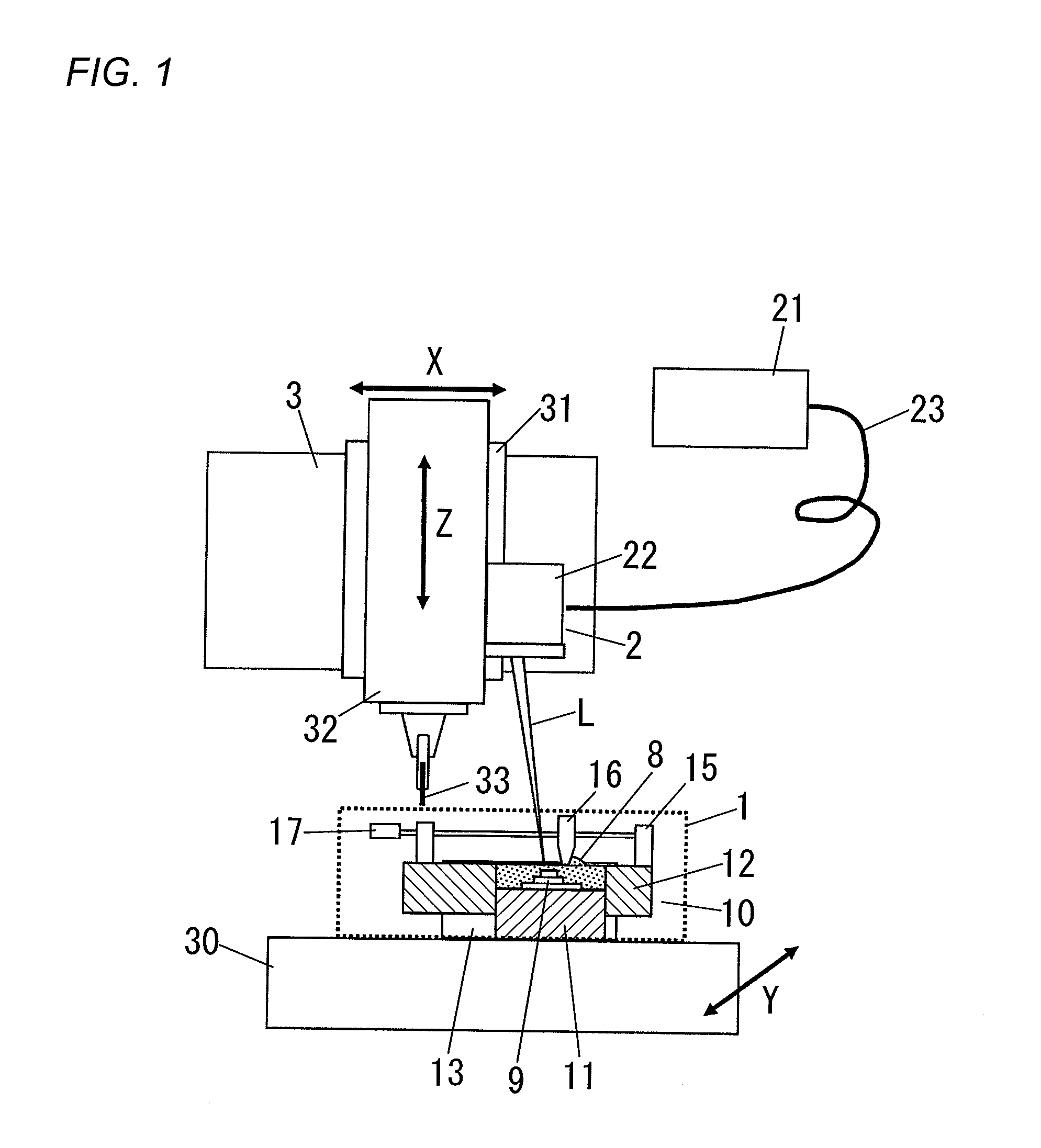
[0064]The milling unit 3 is a numerically controlled machine tool having a table (machining table) 30 and a headstock 31 controllable with respect to at least 3-axis. The headstock 31 has a spindle head 32 equipped with an end mill 33 for grinding, while the shaping unit 1 is disposed on the table 30 of the milling unit 3. A base 11 is fixed to the table 30 to form thereon a lamination object. The optical unit 2 is attached to the headstock 31. In the illustrated embodiment, the spindle head 32 is movable along X-axis and Z-axis, while the table 30 is movable along Y-axis.

[0065]The shaping section 10 of the shaping ...


PUM

PropertyMeasurementUnit
particle sizeaaaaaaaaaa
output poweraaaaaaaaaa
thicknessaaaaaaaaaa

Abstract

A lamination shaping apparatus has a powder layer preparing means and an optical unit which irradiates a light beam to an intended portion of a powder layer so as to sinter or melt for solidifying the portion into a cured layer. Preparation of the powder layer and curing of the cured layer are repeated to fabricate a three-dimensional object in which a plurality of the cured layers are laminated and integrated. The apparatus includes a fixed base carrying thereon the powder layer and the cured layer, an elevator frame surrounding a periphery of the fixed base, and driving means for driving the elevator frame to move vertically. The powder layer is formed within a space above the base and surrounded by an interior surface of the elevator fame such that the powder layer (cured layer) can be stacked on the base with the base being kept at a fixed position, thereby facilitating to fabricate a precisely shaped object.

Description

TECHNICAL FIELD[0001]The present invention relates to a lamination shaping apparatus for fabricating a three-dimensional lamination object with the use of a light beam irradiated to sinter or melt powder material for solidification thereof.BACKGROUND ART[0002]There is already proposed a process of fabricating a lamination object known as a selective powder sintering lamination. The process includes a step of forming a powder layer of inorganic or organic powder, and a step of irradiating a light beam to an intended portion of the powder layer to sinter or melt for solidifying it into a cured layer, these steps being repeated to fabricate the object in which a plurality of the cured layer are laminated and integrated. Japanese patent publication JP2002-115004 A (patent document 1) discloses, in addition to the above, to provide a step of grinding a surface of a precursor of the object between the repeated curing steps of forming the curing layers in order to give a smooth finish to t...

Claims


Application Information

Patent Timeline
Patent Type & Authority Patents(United States)
IPC IPC(8): B29C67/04B28B1/16B29C35/08
CPCB29C67/0077B29C67/0085B22F3/1055B22F3/003B22F2999/00B29C2793/009B22F2003/1056B22F2003/1059B29C64/153B33Y30/00B29C64/25B29C64/268B29C64/371B29C64/188Y02P10/25B22F12/33B22F12/222B22F12/70B22F10/32B22F10/28B22F12/226B22F12/90B22F10/50B22F10/68B22F10/31B22F12/41B29C67/00B22F3/105B22F3/16B29C35/08
Inventor ABE, SATOSHIHIGASHI, YOSHIKAZUYOSHIDA, NORIOFUWA, ISAO
Owner MATSUSHITA ELECTRIC WORKS LTD
Why Eureka
Try Eureka