OSNR measuring apparatus and OSNR measuring method

a technology of optical communication system and measuring apparatus, which is applied in the direction of transmission monitoring, multiplex communication, wavelength-division multiplex system, etc., can solve the problems of increasing the bit error rate (ber) and not being able to accurately measure the signal spectrum, and achieve the effect of reducing the spectral width

Inactive Publication Date: 2011-12-06
FUJITSU LTD
View PDF13 Cites 7 Cited by
  • Summary
  • Abstract
  • Description
  • Claims
  • Application Information

AI Technical Summary

Benefits of technology

[0025]A measuring apparatus according to one aspect of the present invention measures an optical signal noise ratio (OSNR) of a communication channel in a wavelength division multiplexing (WDM) optical communications system. The measuring apparatus includes a reducing unit that reduces spectral width an optical signal sent to a target channel;
[0027]A measuring method according to another aspect of the present invention is of measuring an OSNR of a communication channel in a WDM optical communications system. The measuring method includes reducing spectral width an optical signal sent to a target channel; receiving spectral data measured from the optical signal, and measuring the OSNR of the target channel based on the spectral data.

Problems solved by technology

In systems employing EDFA, amplified spontaneous emission (ASE) is generated becoming noise causing bit error rate (BER) increases.
Along with these advancements, the following problems related to measurement by spectrum analyzer have arisen.
At the same time, if the resolution is increased too much in order to enhance accuracy of ASE component measurement, the entire signal spectrum of the target channel (the signal spectrum 1201) does not fall within the resolution band, leading to the problem of not being able to accurately measure the signal spectrum.

Method used


Image

  • OSNR measuring apparatus and OSNR measuring method
  • OSNR measuring apparatus and OSNR measuring method
  • OSNR measuring apparatus and OSNR measuring method

Examples


Embodiment Construction

[0050]Exemplary embodiments of the present invention will now be described in detail with reference to the accompanying drawings.

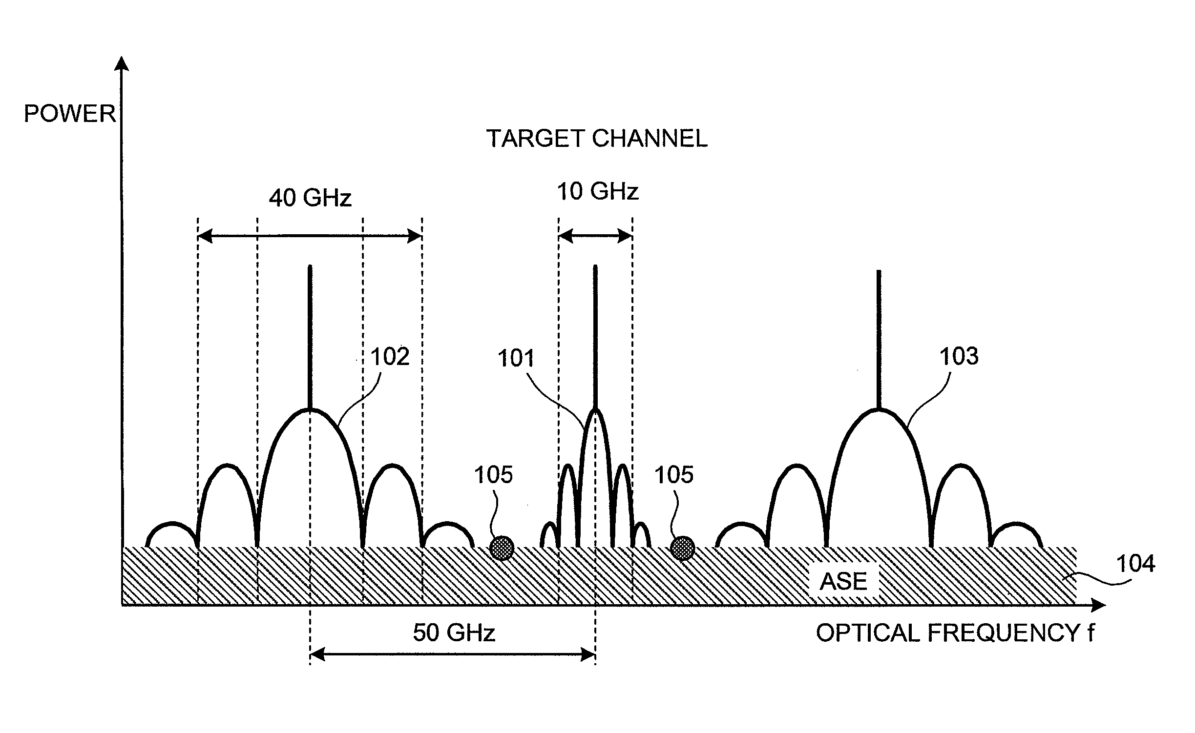
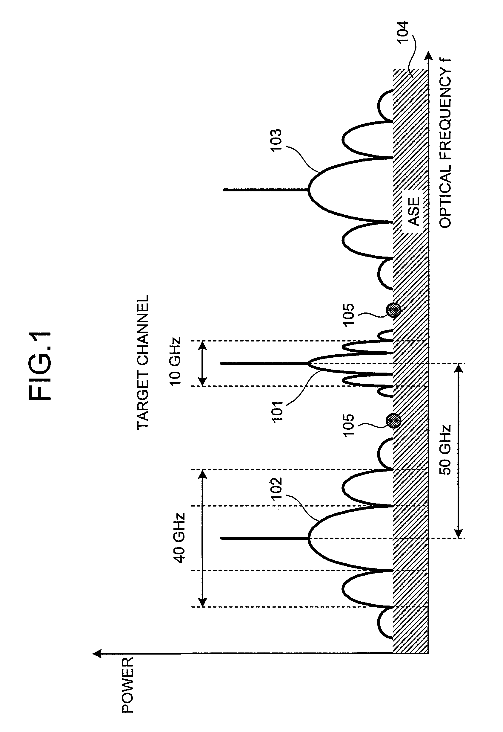
[0051]FIG. 1 is a graph depicting an overview of the present invention. Reference character 101 in FIG. 1 is a signal spectrum of the target channel to be measured (corresponds to the signal spectrum 1201 in FIG. 12). Reference characters 102 and 103 are signal spectrums of adjacent channels relative to the target channel. Reference character 104 is an ASE component arising from EDFA.

[0052]FIG. 1 illustrates a case in which the bit rate of the target channel (refer to reference character 1201 in FIG. 12) decreases temporarily from 10 Gbps to 2.5 Gbps under the control of the of an OSNR measuring apparatus according to embodiments of the present invention. With the decreased bit rate of the target channel, the width of the signal spectrum 101 of the target channel decreases and the overlapping of the signal spectrum 101 with the signal spectrums of the adja...


PUM


Abstract

An apparatus for measuring an OSNR for a communication channel in a WDM optical communications system includes a signal control unit, a receiving unit, and a measuring unit. The signal control unit controls spectral width reduction for an optical signal sent through a target channel. The receiving unit receives spectral data measured from the optical signal received by the target channel under control of the control unit. The measuring unit, based on the spectral data received by the receiving unit, measures the OSNR of the target channel.

Description

CROSS-REFERENCE TO RELATED APPLICATIONS[0001]This application is based upon and claims the benefit of priority from the prior Japanese Patent Application No. 2006-265632, filed on Sep. 28, 2006, the entire contents of which are incorporated herein by reference.BACKGROUND OF THE INVENTION[0002]1. Field of the Invention[0003]The present invention relates to optical signal noise ratio (OSNR) measurement in an optical communication system.[0004]2. Description of the Related Art[0005]Corresponding to an increased volume of information communicated in recent years, research and development related to high capacity, low cost fiber optic communications systems has surged. To further increase capacity and to lower cost, wavelength division multiplexing (WDM), a method for sending multiple wavelengths (that are multiplexed signals) along a single optical fiber, has been and continues to be extensively researched and developed.[0006]Channel spacing, an index of multiplexing, has been standardi...

Claims


Application Information

Patent Timeline
Patent Type & Authority Patents(United States)
IPC IPC(8): H04B10/08H04B17/00H04B10/07H04B10/077H04J14/00H04J14/02
CPCH04B10/07953
Inventor GOTO, RYOSUKE
Owner FUJITSU LTD
Why Eureka
Try Eureka