Pulse grid coherent chromatography method
A technology of coherent tomography and pulse, which is applied in the direction of phase influence characteristic measurement, etc., to achieve strong anti-interference, fast reconstruction and good stability
- Summary
- Abstract
- Description
- Claims
- Application Information
AI Technical Summary
Problems solved by technology
Method used
Image
Examples
Embodiment 1
[0037] Embodiment one: the application embodiment of pulse grating coherence tomography method of the present invention is: (1) use superradiance laser diode (SLD) synthetic light source as broadband low-coherence light source, its central wavelength is 1550nm, and output optical power is 200mW The output light of the light source is coupled to a balanced Mach-Zehnder (MZ) optical modulator with an optical isolator, and the modulation signal of the optical modulator is adjusted so that it outputs pulsed light with a pulse width of 5 ns and an interval of 100 s, or with The ultra-broadband light source with an internal modulator directly outputs pulsed light that meets the requirements; the pulsed light is divided into at least two beams by a semi-transparent mirror with a split ratio of 50:50 and a broadband dielectric film, one of which is projected The reflected light in the suspended particle area returns to the semi-transparent mirror and is used as the signal light; anothe...
Embodiment 2
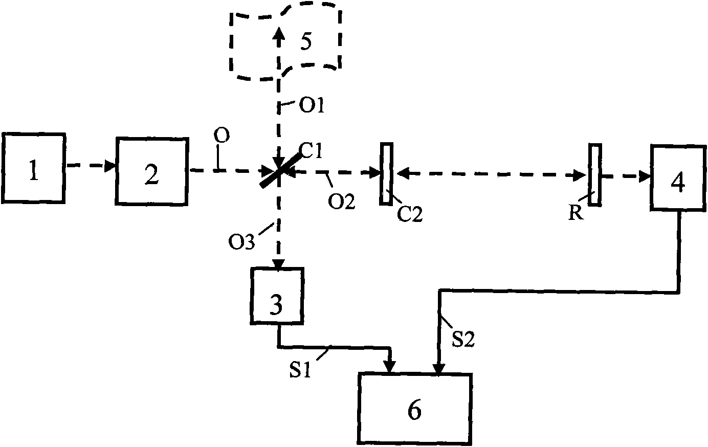
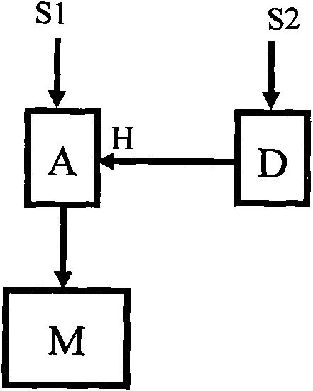
[0038] Embodiment two: see figure 1 , the present embodiment of the pulse grating coherence tomography method is: (1) use the ultrashort pulse light outputted by a low-energy Ti:sapphire femtosecond laser with an isolator or other short pulse light source as the pulse light source 1, the ultrashort pulse light of the ultrashort pulse light The pulse width is 240fs, the central wavelength is 800nm, the spectral width is 10nm, the single pulse energy is less than 2nJ, and the repetition frequency is 1kHz; the ultrashort pulse light is collimated and expanded by the collimator beam expander 2, and then transmitted to the beam splitting ratio The semi-transparent half-mirror C1 of 50:50 broadband dielectric film splits light, wherein a beam of light O1 is projected onto the tomographic suspended particle area 5, and the reflected light of the suspended particle area 5 returns to the half-transparent half-mirror C1 and As a signal light; another beam of light O2 is incident into a...
Embodiment 3
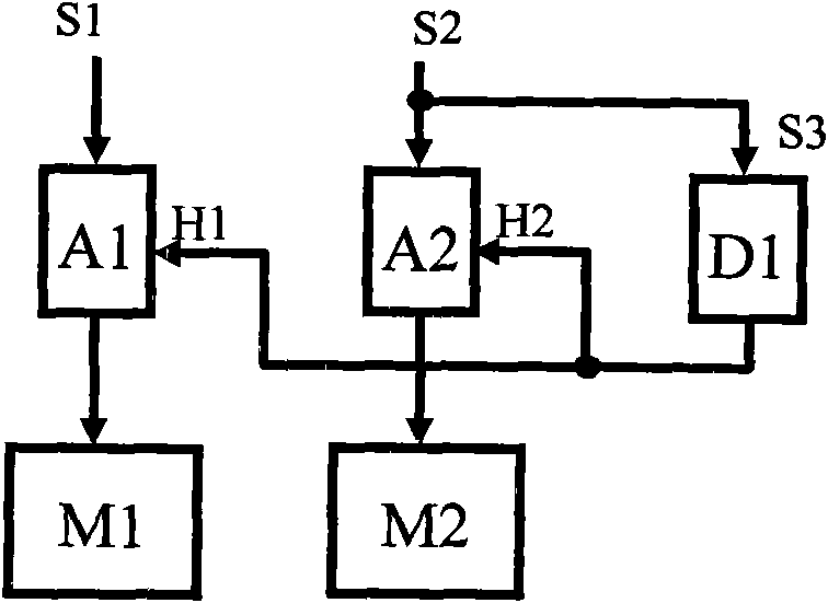
[0039] Embodiment three: see figure 2 , the present embodiment of pulse grid coherence tomography method is: (1) the same as (1) in embodiment one or embodiment two; (2) the same as (2) in embodiment one or embodiment two; ( 3) The difference from (3) in Embodiment 2 is: in the data acquisition and processing system 6, the rising edge of the reference electrical signal S2 is aligned with the peak value of the electrical signal pulse train S1 (available time delay circuit D), the signal after the alignment of the reference electrical signal S2 is used as the sample-hold switch control signal H (also called the sampling time control signal) of the sampler A (including sampling, holding and analog-to-digital conversion functions), and the signal electric pulse The string S1 is sampled and stored in the memory M according to the order of sampling and scanning positions, and the sampled values stored in the memory M are reconstructed according to the order of sampling and scanni...
PUM
| Property | Measurement | Unit |
|---|---|---|
| wavelength | aaaaa | aaaaa |
| transmittivity | aaaaa | aaaaa |
| reflectance | aaaaa | aaaaa |
Abstract
Description
Claims
Application Information
 - R&D
- Intellectual Property
- Life Sciences
- Materials
- Tech Scout
- Unparalleled Data Quality
- Higher Quality Content
- 60% Fewer Hallucinations
Browse by: Latest US Patents, China's latest patents, Technical Efficacy Thesaurus, Application Domain, Technology Topic, Popular Technical Reports.
© 2025 PatSnap. All rights reserved.Legal|Privacy policy|Modern Slavery Act Transparency Statement|Sitemap|About US| Contact US: help@patsnap.com


