
Method of making a distributed bragg mirror

a bragg mirror and distributed technology, applied in the field of optoelectronics, can solve the problems of reducing the contact area between the metal and the upper guide layer, the need to carefully remove the hard mask, and the general imperfection of trench cleaning, so as to achieve good electrical injection, reduce the contact area, and eliminate the effect of difficulty

Pending Publication Date: 2022-06-09
COMMISSARIAT A LENERGIE ATOMIQUE ET AUX ENERGIES ALTERNATIVES
View PDF0 Cites 1 Cited by
  • Summary
  • Abstract
  • Description
  • Claims
  • Application Information

AI Technical Summary

Benefits of technology

The patent describes a method for cleaning and filling first grating trenches with metal in a way that optimizes the performance of distributed feedback (DFB) lasers. The method uses a sacrificial interlayer and a second masking layer to remove residues from the sidewalls and bottom of the trenches. This allows for better electrical injection and improves the contact area between the metal and corrugations, resulting in improved spectral reproducibility and reduced spectral width variability. The method is compatible with a CMOS production line and improves the performance of DFB lasers.

Problems solved by technology

One difficulty with this method concerns the need to carefully remove the hard mask from the trenches before filling with metal.
Trench cleaning is generally imperfect.
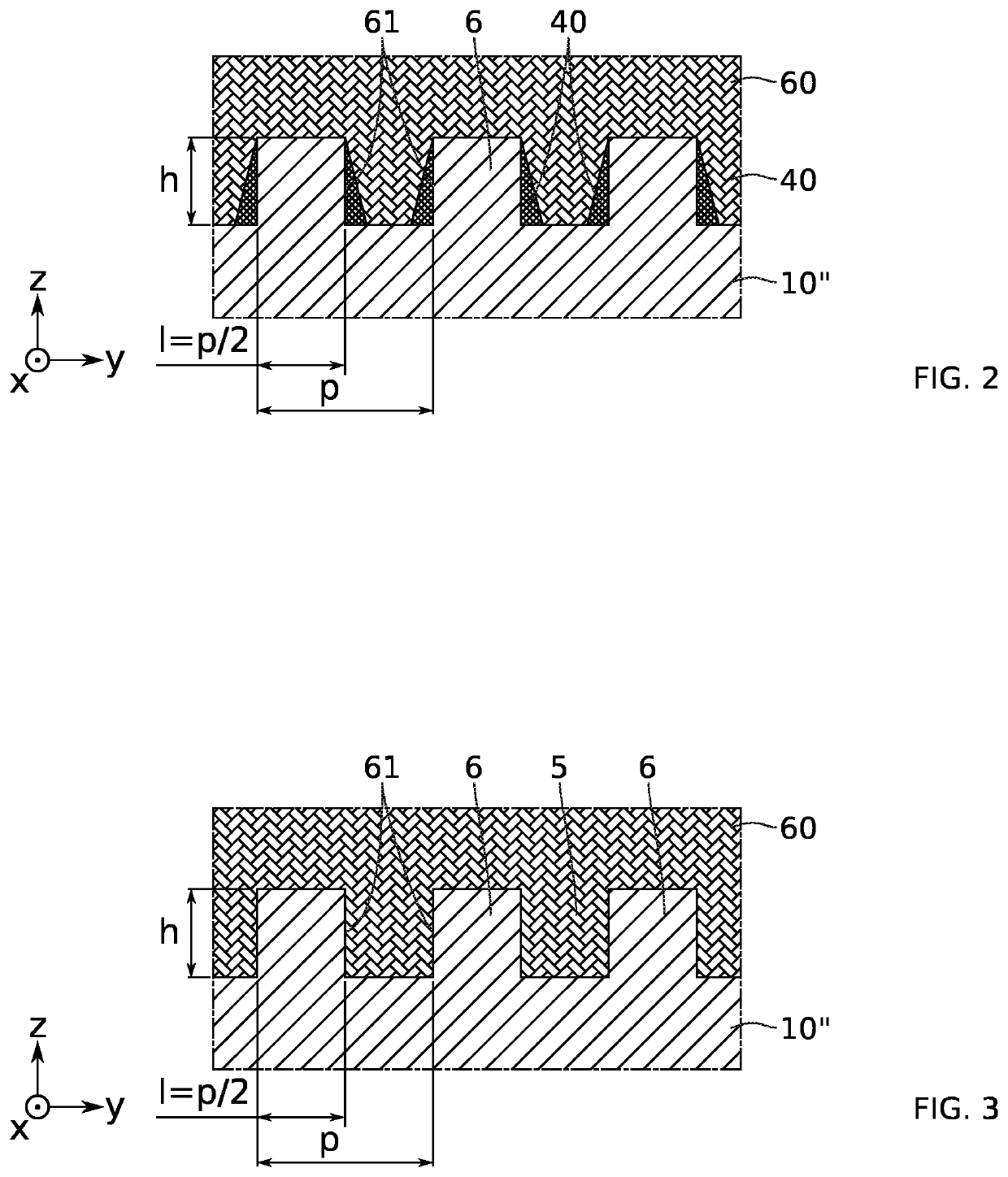
One drawback of this partial filling is that the contact area between the metal and the upper guide layers is thus reduced.
Another drawback caused by the partial filling of the trenches with the metal relates to the optical functioning of the reflector.
The reproducibility of the lasers characteristics is limited.

Method used


Image

  • Method of making a distributed bragg mirror
  • Method of making a distributed bragg mirror
  • Method of making a distributed bragg mirror

Examples


Embodiment Construction

[0040]Before giving a detailed review of embodiments of the invention, optional features are set out below, which can be used in combination with or in replacement of one another.

[0041]According to one example, the sacrificial interlayer is silicon oxide-based and the second masking layer is silicon nitride-based. These two materials have good etch selectivity, typically for hydrofluoric acid-based wet etching. This facilitates removal by lift-off. These materials are also compatible with CMOS technology.

[0042]According to one example, the sacrificial interlayer has a substantially constant thickness e comprised between 100 nm and 300 nm. It can typically be formed by conformal deposition. A constant thickness allows for better control of the lift-off method.

[0043]According to one example, the first trenches are formed by anisotropic etching in a third direction z normal to the first and second directions x, y.

[0044]According to one example, the sacrificial interlayer is removed by ...


PUM

PropertyMeasurementUnit
thicknessaaaaaaaaaa
thicknessaaaaaaaaaa
thicknessaaaaaaaaaa

Abstract

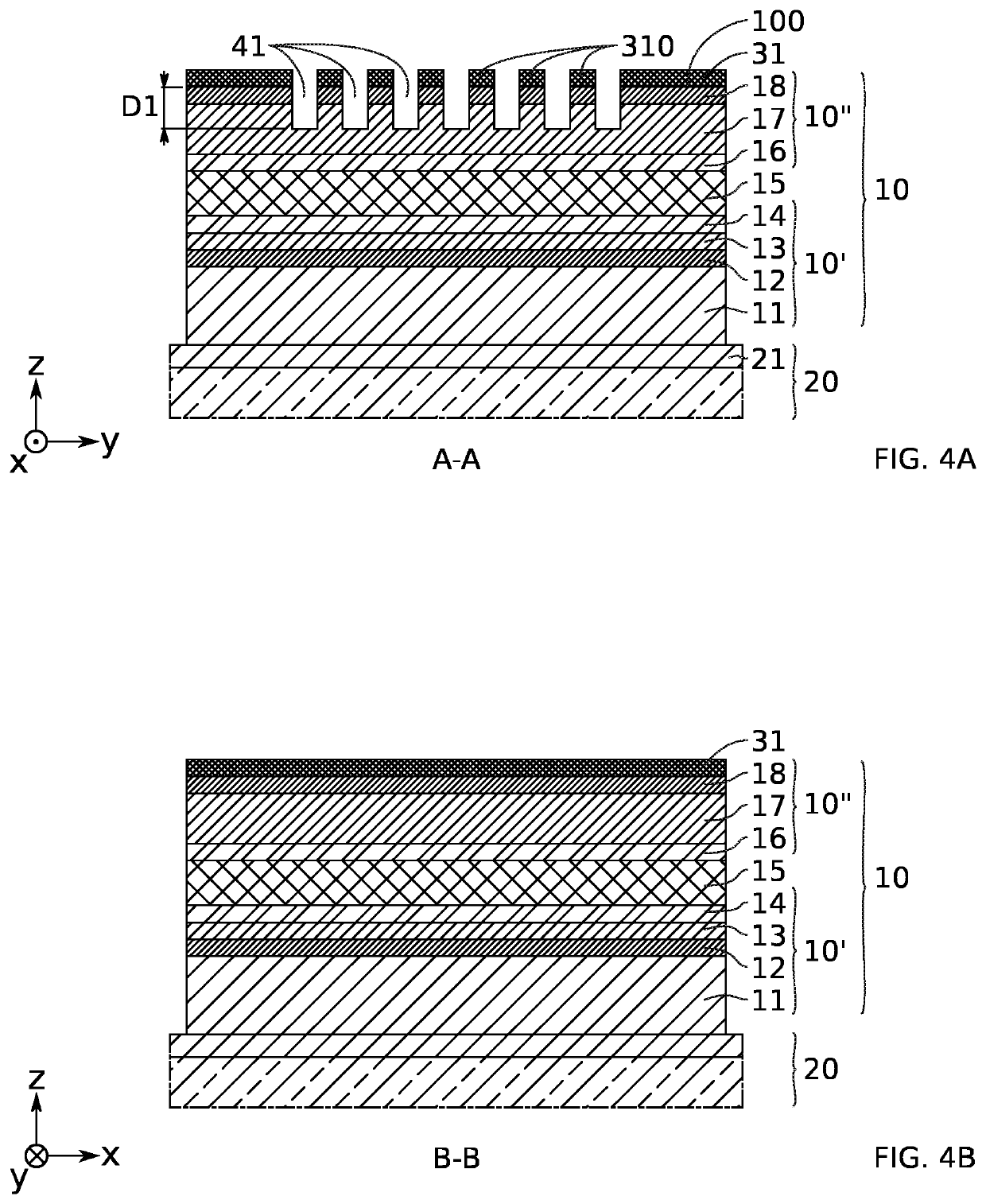
A method for forming a Bragg reflector includes after forming first trenches in the stack, which are intended to form structures of the distributed Bragg reflector, forming a sacrificial interlayer at least in the first trenches, depositing a second masking layer at least inside the first trenches, forming second trenches intended to form sidewalls of the laser, removing the second masking layer from inside the first trenches, removing said sacrificial interlayer so as to remove, by lift-off, residues of the second masking layer that remain inside the first trenches, and filling said first trenches with at least one metal material.

Description

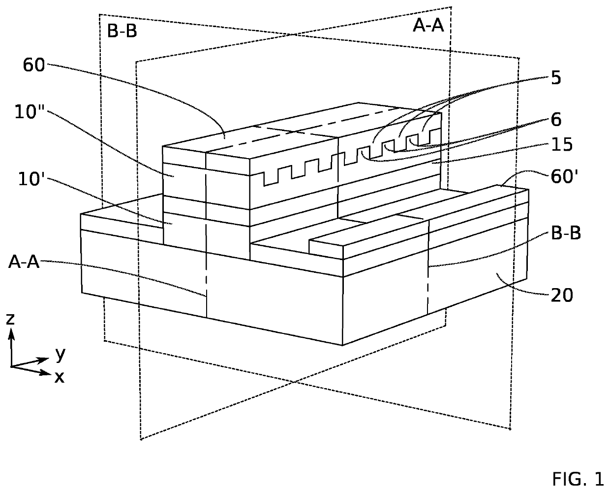
TECHNICAL FIELD[0001]The present invention relates to the field of optoelectronics. It can be implemented to produce light-emitting components, in particular emitting light in the mid-infrared (MIR) region. One particularly advantageous application is that of the production of distributed Bragg reflectors for quantum cascade laser sources using CMOS-compatible technology. One specific example application is that of environmental sensors using MIR sources.PRIOR ART[0002]A Bragg reflector allows light radiation of a given wavelength λ to be reflected with a reflectivity R greater than 99%. Such a reflector 65 typically comprises a periodic array of grating structures 5, 6 with different refractive indices (FIG. 1). Partial reflection of the light radiation occurs with each index change. For a grating period in the order of λ / 2n, where n is the effective refractive index, the partial reflections combine with constructive interference, and the structures “distributed” along the grating ...

Claims


Application Information

Patent Timeline
Patent Type & Authority Applications(United States)
IPC IPC(8): H01S5/125
CPCH01S5/125H01S5/12H01S5/1231H01S5/22H01S5/3401H01S2301/176H01S5/209H01S5/2202H01L21/3065
Inventor FOURNIER, MARYSEREBOUD, VINCENTFEDELI, JEAN-MARC
Owner COMMISSARIAT A LENERGIE ATOMIQUE ET AUX ENERGIES ALTERNATIVES
Learn More