Helical inner diameter groove journal bearing

a journal bearing and inner diameter technology, applied in the field of bearing systems, to achieve the effect of enhancing the flow of lubricant, facilitating shaft movement, and high viscosity

Active Publication Date: 2011-12-13
GARRETT TRANSPORATION I INC
View PDF12 Cites 11 Cited by
  • Summary
  • Abstract
  • Description
  • Claims
  • Application Information

AI Technical Summary

Benefits of technology

[0025]A bearing in a bearing system can be viewed as having a loaded side and an unloaded side (i.e., a unidirectional radial force vector). As described herein, helical paths provide suitable lubricant flow to both loaded and unloaded sides of an exemplary bearing. Lubricant flow through an unloaded side of a bearing cools the bearing and the shaft. Such cooling acts to reduce local temperature maxima that can cause coking.
[0027]As described herein, shape of a helical groove ensures that lubricant can enter between a shaft and bearing efficiently to allow generation of a pressure wedge that supports loads being imparted to the bearing from the shaft. An exemplary groove shape may be a ramped surface (e.g., as used in thrust bearings). A turbocharger may include an external high pressure lubricant supply to overcome pressures in a bearing to thereby ensure that the exemplary bearings experience adequate lubricant flow to support the shaft and carry away heat.
[0028]As described herein, an exemplary bearing system keeps a shaft and the bearings cooler. Further, cooler lubricant typically has higher viscosity which is more effective at separating surfaces.
[0029]As described herein, an exemplary pair of bearings (or a unitary bearing) includes three helical grooves for a turbine side shaft journal surface and three helical grooves for a compressor side shaft journal surface. Such exemplary bearings (or bearing) are (is) optionally used for a smaller sized turbocharger. In such an example, outer surface grooves may be present to enhance flow of lubricant to openings that connect to the helical grooves. Such outer surface grooves may have an arc span measured in degrees. For example, each outer groove may have an arc span of about 15 degrees. A sum of the arc spans is typically less than 360 degrees; noting that where each bearing has an outer channel with an arc span of 360 degrees, higher shaft motion has been observed.

Problems solved by technology

While various characteristics associated with semi-floating bearings may be disadvantageous, an exemplary semi-floating bearing may include helical grooves.

Method used


Image

  • Helical inner diameter groove journal bearing
  • Helical inner diameter groove journal bearing
  • Helical inner diameter groove journal bearing

Examples


Embodiment Construction

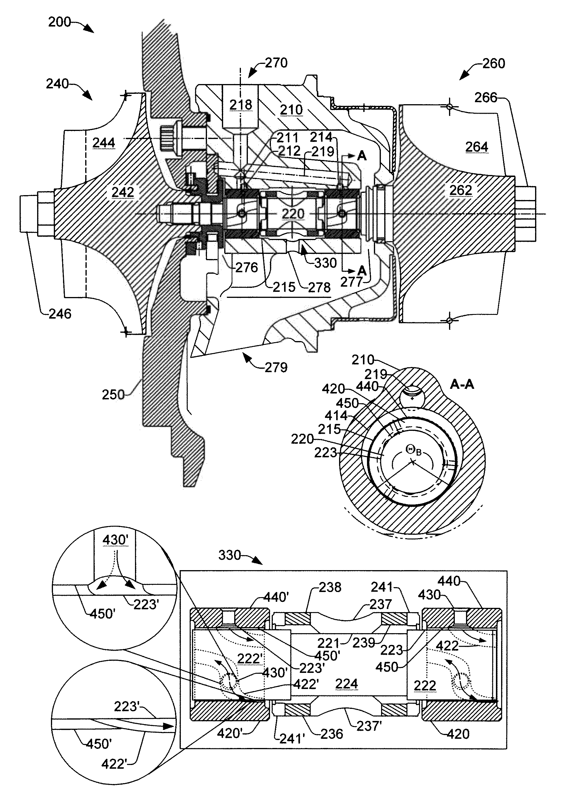
[0042]FIG. 3 shows an exemplary bearing system 330 in the center housing 210. A cross-sectional view of the bearing system 330 along a line A-A shows the bore 219 joining a semi-annular groove 414 (e.g., shaped differently than the groove 214), an exemplary journal bearing 420 and the shaft 220. The bearing 420 includes an outer surface 440 and an inner surface 450. During operation, a damping film forms between the outer surface 440 and the bore 215 of the housing 210 and a lubricant film forms between the inner surface 450 and the outer surface 223 of the shaft 220. As mentioned, the bearing 420 may float in the bore 215 as supported by the damping film. While the damping film and the lubricant film both participate in heat transfer, the damping film also acts to absorb vibration energy that may affect rotation of the shaft 220 in the bearing 420.

[0043]In FIG. 3, the close-up cross-section of the bearing system 330 shows a turbine side bearing 420, a compressor side bearing 420′ a...


PUM

PropertyMeasurementUnit
temperaturesaaaaaaaaaa
angleaaaaaaaaaa
azimuthal angleaaaaaaaaaa

Abstract

An exemplary bearing assembly includes a turbine side journal bearing with helical grooves along an inner journal surface where each helical groove includes a lubricant opening and opposing arms where each arm terminates at a respective axial surface of the journal bearing; a compressor side journal bearing with helical grooves along an inner journal surface where each helical groove includes a lubricant opening and opposing arms where each arm terminates at a respective axial surface of the journal bearing; and a spacer to space the turbine side journal bearing and the compressor side journal bearing along an axis. Various other exemplary devices, systems, methods, etc., are also disclosed.

Description

TECHNICAL FIELD[0001]Subject matter disclosed herein relates generally to turbomachinery for internal combustion engines and, in particular, to bearing systems.BACKGROUND[0002]A conventional turbocharger typically relies on a center housing rotating assembly (CHRA) that includes a turbine wheel and a compressor wheel attached to a shaft rotatably supported in a center housing by one or more bearings. During operation, and directly after operation, heat energy from various sources can cause components to reach temperatures in excess of 1000 degrees Fahrenheit (538 degrees Celsius). Sources of heat energy include viscous shearing of lubricant films (e.g., lubricant between a rotating shaft and a bearing surface), viscous heating of inlet gas, exhaust heat, frictional heating, etc. Factors such as mass of the rotating components, lubricant properties, rotational speeds, etc., can affect heat generation.[0003]High temperatures can cause carbonization of carbonaceous lubricants (e.g., oi...

Claims


Application Information

Patent Timeline
Patent Type & Authority Patents(United States)
IPC IPC(8): F16C33/10
CPCF01D25/16F01D25/166F16C17/18F05D2220/40Y10T29/49643Y10T29/49641Y10T29/49636Y10T29/49645F05D2250/25F05D2260/98F16C17/02F16C17/26F16C2360/24
Inventor GUTKNECHT, DANIEL A.
Owner GARRETT TRANSPORATION I INC
Why Eureka
Try Eureka