Electron beam apparatus and method of operating the same

a technology of electron beam and apparatus, which is applied in the direction of magnetic discharge control, instruments, heat measurement, etc., can solve the problems of difficult detection of backscattered electron difficult detection of backscattered electrons and secondary electrons produced from specimens, etc., to prevent unnecessary deflection of primary electron beam and prevent resolution degradation

Active Publication Date: 2011-12-13
JEOL LTD
View PDF9 Cites 2 Cited by
  • Summary
  • Abstract
  • Description
  • Claims
  • Application Information

AI Technical Summary

Benefits of technology

[0011]It is a further object of the present invention to provide an electron beam apparatus which can prevent undesired deflection of the primary electron beam during the detection and thus can prevent deterioration of resolution. It is an additional object of the present invention to provide a method of operating this electron beam apparatus.
[0014]In the present invention, the electrode for producing an electric field that attracts the electrons produced from the specimen in response to the irradiation by the primary electron beam is mounted on the electron detector located above the objective lens. The correction coils for correcting deflection of the electron beam caused by the electric field are mounted below the electron detector. The electrons to be detected (such as backscattered electrons and secondary electrons) reaching above the objective lens are attracted toward the electron detector by the action of the electric field produced by the electrode. Consequently, if the electron detector is located above the objective lens, the detector can detect the electrons efficiently.
[0016]The primary electron beam may be deflected unnecessarily due to the action of the electric field produced by the electrode. The deflection of the primary electron beam can be corrected by the action of a magnetic field produced when the correction coils are excited. In consequence, the unnecessary deflection of the primary electron beam can be prevented. Hence, during observation, deterioration of resolution can be prevented.

Problems solved by technology

In an electron beam apparatus where an electron detector is located above an objective lens, if the primary electron beam is accelerated by low accelerating voltages, it has been difficult to detect backscattered electrons produced from the specimen in response to irradiation by the primary electron beam.
Furthermore, it has been difficult to detect both backscattered electrons and secondary electrons produced from the specimen.

Method used


Image

  • Electron beam apparatus and method of operating the same
  • Electron beam apparatus and method of operating the same
  • Electron beam apparatus and method of operating the same

Examples


Embodiment Construction

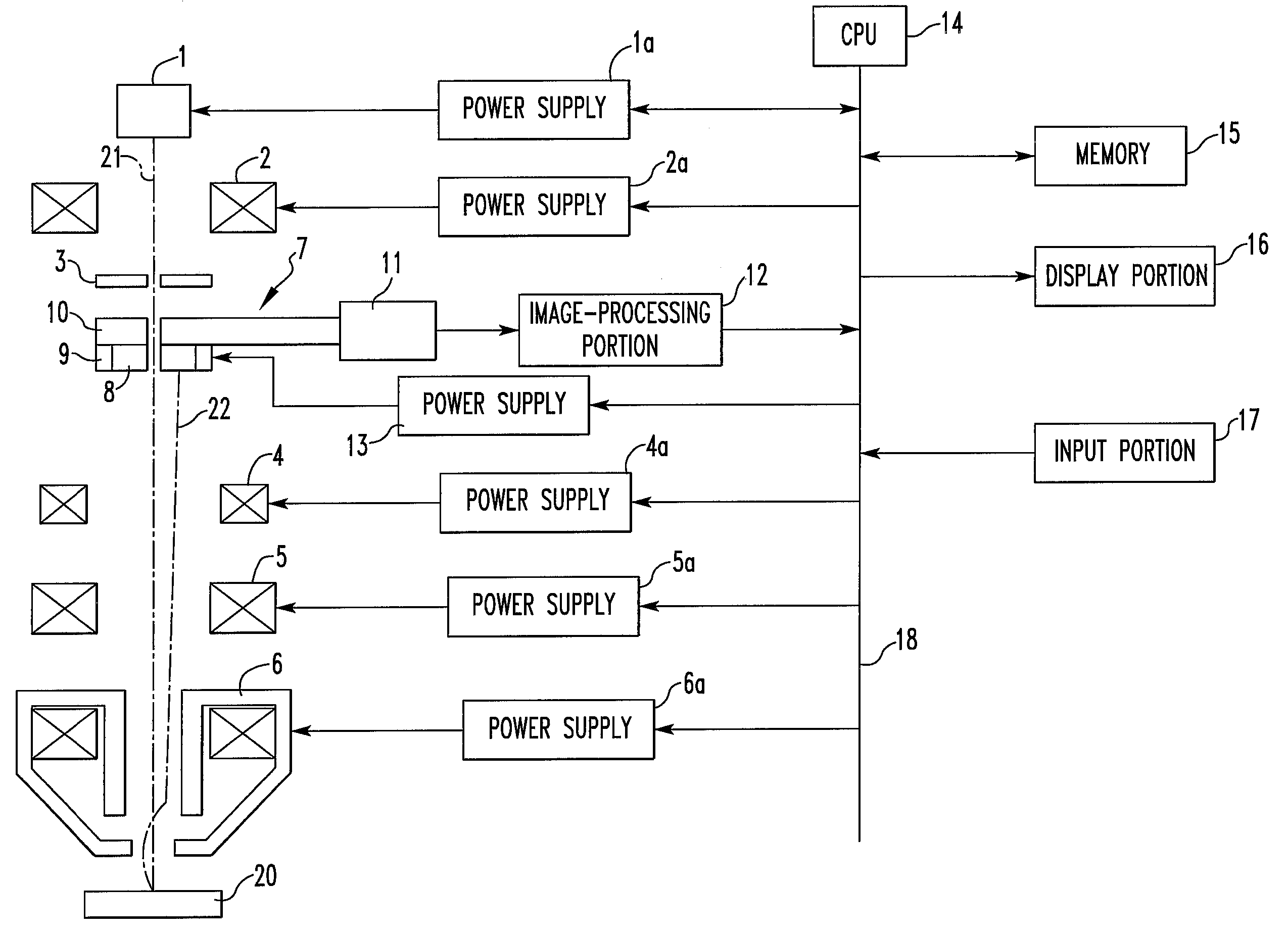
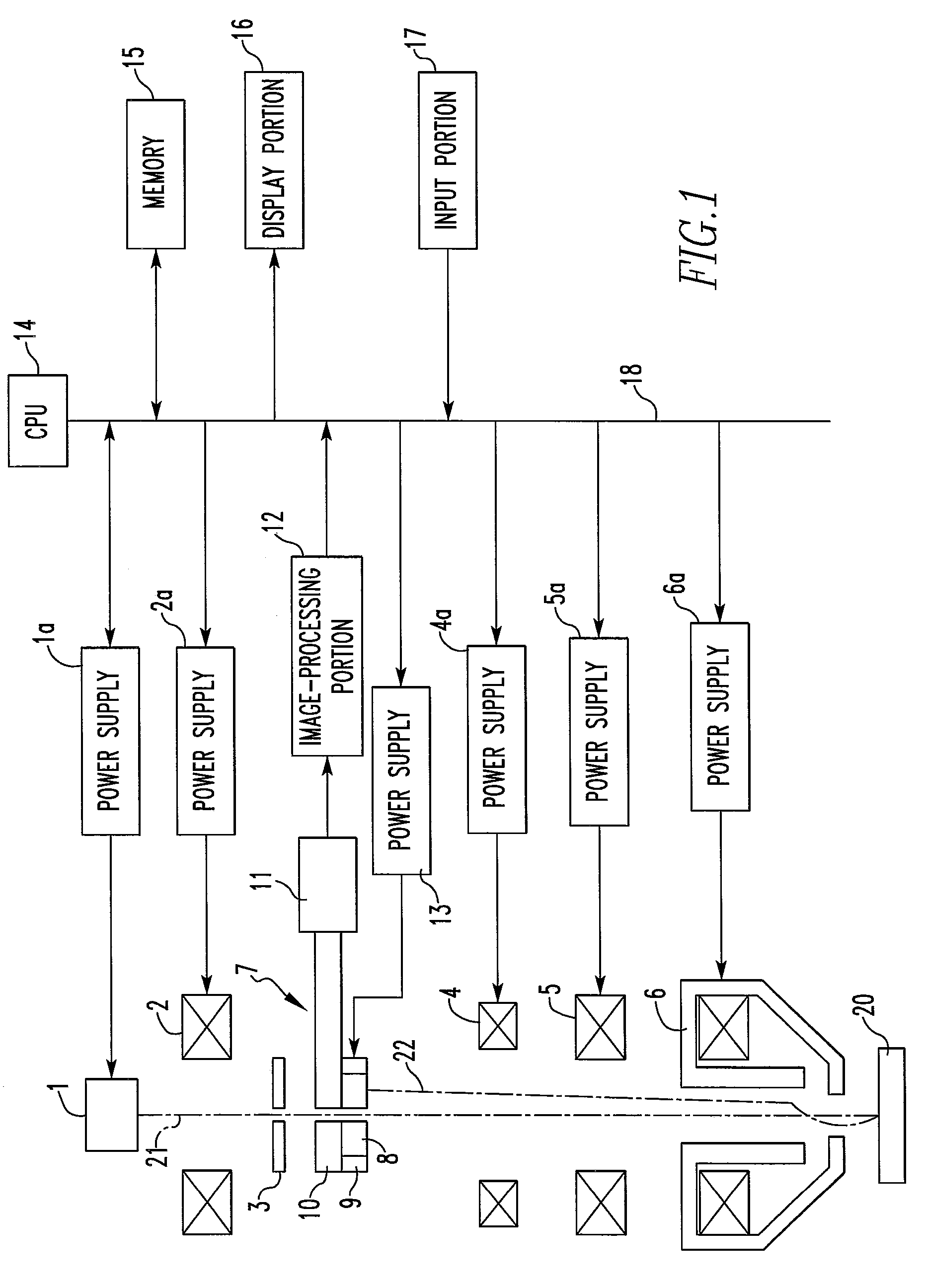
[0020]The present invention is hereinafter described in detail with reference to the drawings. FIG. 1 is a schematic block diagram of an electron beam apparatus according to one embodiment of the present invention. This apparatus has the structure of a scanning electron microscope.

[0021]The electron beam apparatus has an electron beam source 1 consisting of an electron gun. The beam source 1 emits an electron beam (primary electron beam) 21 toward a specimen 20, the beam being accelerated by a given accelerating voltage. The beam 21 emitted from the electron beam source 1 in this way is focused by a condenser lens 2 and passes through a through-hole in an objective aperture 3.

[0022]The electron beam 21 passed through the hole in the objective aperture 3 passes through a through-hole in an electron detector 7 located below (on the downstream side of) the aperture 3. Then, the beam 21 impinges on an objective lens 6 through correction coils 4 and scan coils 5.

[0023]The front end of th...


PUM


Abstract

An electron beam apparatus is offered which can well detect backscattered electrons or both backscattered electrons and secondary electrons if an electron detector is disposed above an objective lens in the apparatus. The electron beam apparatus has an electron beam source for emitting an electron beam accelerated by a given accelerating voltage, the objective lens for focusing the electron beam emitted from the beam source onto a specimen, scan coils for scanning the focused beam over the specimen, and the electron detector located above the objective lens and provided with a hole permitting passage of the beam. The detector has an electrode for producing an electric field that attracts the electrons produced from the specimen in response to the electron beam irradiation. Correction coils for correcting deflection of the beam caused by the electric field are located below the detector.

Description

BACKGROUND OF THE INVENTION[0001]1. Field of the Invention[0002]The present invention relates to an electron beam apparatus, such as a scanning electron microscope, and to a method of operating the apparatus.[0003]2. Description of Related Art[0004]In a scanning electron microscope, a primary electron beam that is accelerated and released from an electron beam source, such as an electron gun, is brought to a focus by the lens action of an objective lens such that the diameter of the probe is reduced on a specimen surface. Under this condition, the beam is scanned in two dimensions across the specimen surface. As a result, electrons, such as secondary electrons and backscattered electrons, are produced from the specimen and detected as a signal.[0005]A detector for detecting such electrons is located below or above the objective lens. The output signal from the detector representative of the detected electrons is amplified as an image signal and sent to an image-processing circuit. T...

Claims


Application Information

Patent Timeline
Patent Type & Authority Patents(United States)
IPC IPC(8): H01J37/28H01J37/244
CPCH01J37/153H01J37/244H01J37/28H01J2237/15H01J2237/2443H01J2237/24475H01J2237/2448
Inventor KAZUMORI, HIROYOSHI
Owner JEOL LTD
Why Eureka
Try Eureka