Optimal estimation of transducer parameters

a transducer and parameter technology, applied in the field of optimal estimation of transducer parameters, can solve the problems of significant errors in the estimated nonlinear parameters, method time-consuming, and cannot be extended to a multi-tone stimulus, and achieve the effects of minimal processing capacity, low cost of system, and sufficient amplitude and bandwidth

Active Publication Date: 2011-12-13
KLIPPEL WOLFGANG
View PDF19 Cites 10 Cited by
  • Summary
  • Abstract
  • Description
  • Claims
  • Application Information

AI Technical Summary

Benefits of technology

[0021]There is thus a need for an identification system which estimates the nonlinear parameters Pn and the linear parameters Pl of the model without a systematic error (bias) if the measured signals are disturbed by noise or there are imperfections in the modeling of the transducer. The free parameters of the model should be identified by exciting the transducer with a normal audio signal (e.g. music), a synthetic test signal (e.g. noise) or a control signal as used in active noise cancellation having sufficient amplitude and bandwidth to provide persistent excitation. The transferred signal shall not or only minimally be changed by the identification system to avoid any degradation of the subjectively perceived sound quality. A further object is to realize an identification system for transducers comprising a minimum of elements and requiring minimal processing capacity in a digital signal processor (DSP) to keep the cost of the system low.SUMMARY OF THE INVENTION
[0022]According to the invention, the nonlinear parameters Pn are estimated by minimizing the cost function:Cn=E{en(t)2}→Minimum  (24)which considers the nonlinear error part en only. In this case, the correlation:E{Gn(t)en(t)}=0  (25)between nonlinear error part en(t) and nonlinear gradient signal Gn(t) vanishes. Thus, a systematic error (bias) in the estimated value of the nonlinear parameter Pn can be avoided.
[0049]If the nonlinear parameters Pn have been estimated without bias and the nonlinear error en(t) disappears, the linear parameters Pl can be estimated without bias by minimizing the cost function C in Eq. (15).
[0050]The current invention has the benefit that the linear and nonlinear parameters can be determined without a systematic error (bias), even if the modeling of the linear properties of the transducer is not perfect. This reduces the effort in modeling complicated mechanisms (e.g., creep of the suspension) and makes it possible to use models with lower complexity and a minimal number of free parameters. This is beneficial for speeding up the identification process, improving the robustness and reducing implementation cost.

Problems solved by technology

This approach is not applicable to an electro-acoustical transducer as the computational load can not be processed by available digital signal processors (DSPs).
This method is time consuming and can not be extended to a multi-tone stimulus because the distortion components interfere if the number of fundamental tones is high.
However, there are always differences between the theoretical model and the real transducer which causes significant errors in the estimated nonlinear parameters (bias).
(15) may also cause a systematic bias in the estimation of the nonlinear parameters Pn.
This demand can not be realized in many practical applications.
The eddy currents induced in the pole plate of a loudspeaker also generate a high complexity of the electrical input impedance.
In addition, loudspeakers also behave as time varying systems where aging and changing ambient conditions (temperature, humidity) cause a mismatch between reality and model which increases the residual error signal er(t).

Method used


Image

  • Optimal estimation of transducer parameters
  • Optimal estimation of transducer parameters
  • Optimal estimation of transducer parameters

Examples


Embodiment Construction

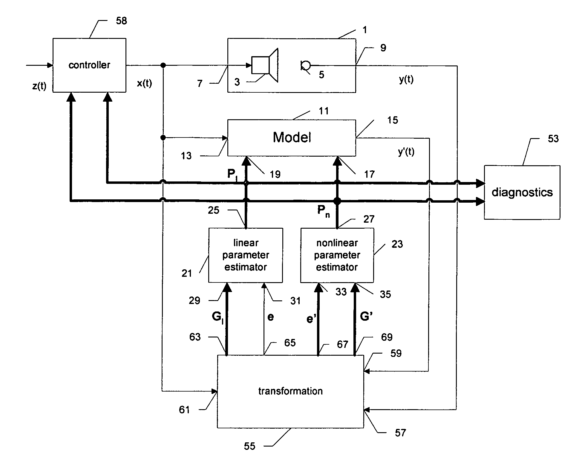
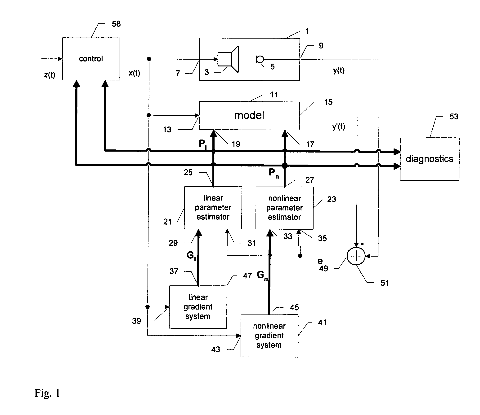
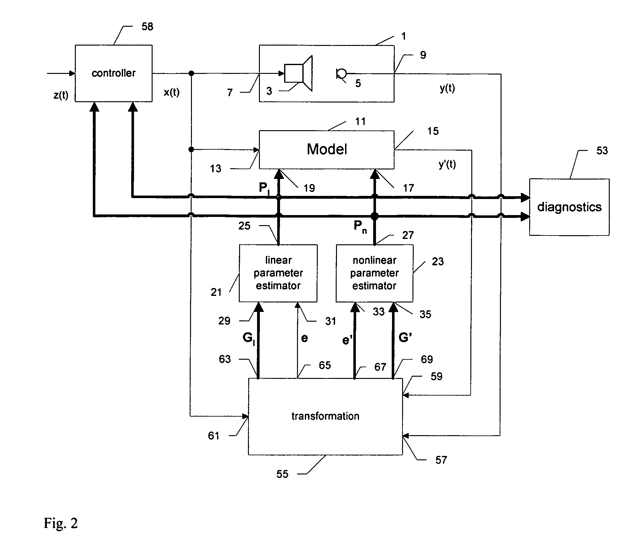
[0058]FIG. 1 is a general block diagram showing a parameter identification system for measurement, diagnostics and control application in the prior art. The real transducer system 1 consists of a loudspeaker 3 (actuator) converting an electrical input signal x(t) (e.g., voltage at the terminals) at input 7 into a acoustical signal and a microphone 5 (sensor) converting an acoustical signal into an electrical signal y(t) at output 9 which is supplied to the non-inverting input of an amplifier 51. The transfer behavior of transducer system 1 is represented by Eq. (1). The input signal x(t) is also supplied via input 13 to a model 11. The model 11 describes the linear and nonlinear transfer behavior of transducer system 1 and generates an output signal y′(t) at output 15 which is supplied to the inverting input of the amplifier 51. The nonlinear Eq. (8) describes the transfer behavior of the model 11, whereas the product of the linear parameter Pl and linear gradient vector Gl(t) is re...


PUM


Abstract

The invention relates to an arrangement and method for estimating the linear and nonlinear parameters of a model 11 describing a transducer 1 which converts input signals x(t) into output signals y(t) (e.g., electrical, mechanical or acoustical signals). Transducers of this kind are primarily actuators (loudspeakers) and sensors (microphones), but also electrical systems for storing, transmitting and converting signals. The model describes the internal states of the transducer and the transfer behavior between input and output both in the small-and large-signal domain. This information is the basis for measurement applications, quality assessment, failure diagnostics and for controlling the transducer actively. The identification of linear and nonlinear parameters Pl and Pn of the model without systematic error (bias) is the objective of the current invention. This is achieved by using a transformation system 55 to estimate the linear parameters Pl and the nonlinear parameters Pn with separate cost functions.

Description

BACKGROUND OF THE INVENTION[0001]1. Field of the Invention[0002]The invention relates generally to an arrangement and a method for estimating the linear and nonlinear parameters of a model describing a transducer which converts input signals (e.g., electrical, mechanical or acoustical signals) into output signals (e.g., electrical, mechanical or acoustical signals). Transducers of this kind are primarily actuators (such as loudspeakers) and sensors (such as microphones), but also electrical systems for storing, transmitting and converting signals. The model is nonlinear and describes the internal states of the transducer and the transfer behavior between input and output at small and high amplitudes. The model has free parameters which have to be identified for the particular transducer at high precision while avoiding any systematic error (bias). The identification of nonlinear systems is the basis for measurement applications, quality assessment and failure diagnostics and for con...

Claims


Application Information

Patent Timeline
Patent Type & Authority Patents(United States)
IPC IPC(8): G06F7/60G06F17/10
CPCG06F17/5036H04R3/002H04R5/04G06F30/367
Inventor KLIPPEL, WOLFGANG
Owner KLIPPEL WOLFGANG
Why Eureka
Try Eureka