
Low-temperature laser spot impact welding driven without contact

a laser spot and impact welding technology, applied in the field of collision joining, can solve the problems of brittle system, limited alloy, poor mechanical performance, etc., and achieve the effect of reducing laser energy, absorbing optical energy, and easy ablation

Active Publication Date: 2011-12-27
THE OHIO STATES UNIV
View PDF29 Cites 10 Cited by
  • Summary
  • Abstract
  • Description
  • Claims
  • Application Information

AI Technical Summary

Benefits of technology

The present invention provides a method for using laser technology to create a strong mechanical bond between two parts by using intense laser discharges or other energy sources to provide a mechanical impulse to a metal surface. This technique allows for precise placement of the laser beam and timing accuracy, resulting in welds that can be directed to specific locations and at precise times. The invention also provides a method for joining the tab and end of a beverage can, which allows for the use of a thinner section of higher strength material and saves weight and cost. The invention also includes a system for producing a spot impact weld and a spot welded product.

Problems solved by technology

The joining of similar and dissimilar metals is a technical topic that is of great practical importance and can be quite problematic.
First, it is limited to alloys that make compatible pairs when mixed.
Many alloy systems will form brittle intermetallics when mixed and this provides poor mechanical performance.
Second, the heat that is deposited in the weld zone usually dramatically softens the material adjacent to the weld and the melted and solidified material itself may be quite weak or brittle.
As a result, the metals that make up welded structures typically have quite low strength in the region that makes up the weld.
These techniques can all have significant disadvantages for when considering specific applications.
Similar or dissimilar metals can be joined in this manner as there is not sufficient time or temperature for the formation of brittle intermetallics.
However, explosion welding has some disadvantages, not the least of which are the safety and containment issues associated with the process.
Additionally, it is very difficult to couple explosives or magnetic pulse energy to small structures (on the order of millimeters or smaller).
For these reasons, the potential for joining materials using high velocity collisions that do not require the use of explosives offers the potential for joining otherwise difficult (or impossible) to join materials.
This requires significant ductility of the material that makes up the can end.
In principle the tab could also be spot welded to the end, however, this would produce a severely weakened zone in the proximity of the weld nugget and again this would necessitate a thicker than optimum weld zone.

Method used


Image

  • Low-temperature laser spot impact welding driven without contact
  • Low-temperature laser spot impact welding driven without contact
  • Low-temperature laser spot impact welding driven without contact

Examples


Embodiment Construction

)

[0024]In accordance with the foregoing summary, the following presents a detailed description of the preferred embodiments of the invention that is currently considered to be the best mode.

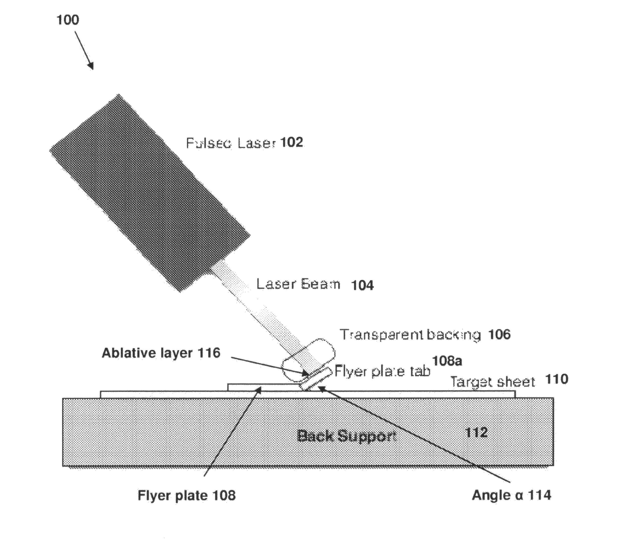
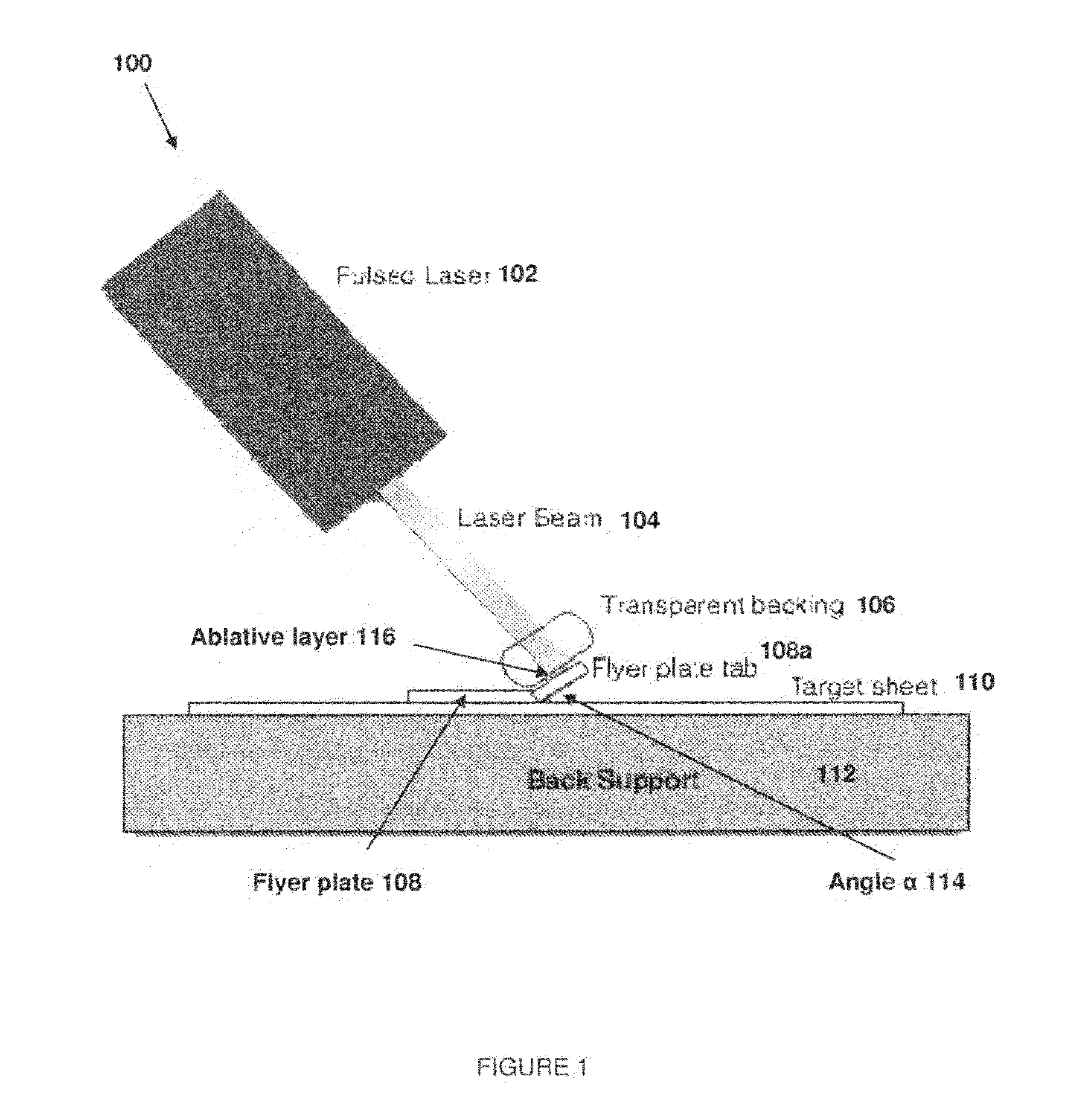
[0025]FIG. 1 depicts a system 100 for the practice of the present invention in accordance with one embodiment thereof. The system comprises a high powered laser 102 aimed at a flyer plate 108 positioned on the target sheet 110 to which the flyer plate tab 108a will be welded. The target sheet is supported by a mechanically-stiff back support 112. The angle α114 between the flyer plate tab 108a and target sheet 110 is about 15 degrees, but may fall in the range of from about 5 degrees to about 20 degrees. An offset distance without an angle can also permit the two surfaces to impact at an appropriate angle for impact welding.

[0026]The high power pulsed laser 102 is capable of depositing from 0.1 to 100 Joules of optical energy focused in a local area on the top surface of flyer plate tab 108a in a...


PUM

PropertyMeasurementUnit
angleaaaaaaaaaa
impact angleaaaaaaaaaa

Abstract

A laser, aimed at a flyer plate tab, causes optical energy to be directed at the tab, specifically, at a top surface thereof. Energy impacting the tab accelerates the tab out of an initial bent position, straightening it into an impact with a target sheet. The impact occurs in excess of 100 m / s, resulting in a metallurgical bond between the tab and the target sheet. The laser preferably strikes the top surface in a normal direction, based upon an initial angularity of the tab relative to the target. The laser emission, preferably in the range of 1 to 100 Joules delivered in a microsecond, may be augmented by an ablative layer on the top surface or a transparent covering on the top surface that reacts against the expanding gas from ablative activity on the top surface. The weld is formed without physical contact between the welding device and the tab.

Description

CROSS-REFERENCE TO RELATED APPLICATIONS[0001]This application is a national stage entry of, and claims the benefit of priority under 35 USC 365 to, PCT / US2009 / 036499, filed 9 Mar. 2009, which is in turn a non-provisional of, and claims the benefit of priority under 35 USC 119 to, U.S. provisional application 61 / 034,574, filed on 7 Mar. 2008. Both applications are incorporated by reference as if fully recited herein.TECHNICAL FIELD[0002]The present invention is in the field of collision joining. Specifically, the present invention relates to the use of a laser or some other energy source such as focused non-coherent light or by vaporization of a metal foil by an electrical discharge to impart momentum to an article to be collision joined.BACKGROUND OF THE ART[0003]The joining of similar and dissimilar metals is a technical topic that is of great practical importance and can be quite problematic. This is an issue that is important in a variety of industries such as the automotive, aer...

Claims


Application Information

Patent Timeline
Patent Type & Authority Patents(United States)
IPC IPC(8): B23K26/00B23K20/12
CPCB23K26/22B23K20/06B23K2201/125B23K2101/125
Inventor DAEHN, GLENN S.LIPPOLD, JOHN C.
Owner THE OHIO STATES UNIV
Learn More