Cotton picker spindle with grease reservoir and a grease and dirt seal

a technology of grease reservoir and spindle, which is applied in the field of spindles, can solve the problems of limited machine productivity, high density of spindles, and substantial weight of the driven portion of the row unit, and achieves the effects of reducing weight and mass in motion, reducing spindle drag, and increasing service interval

Active Publication Date: 2012-01-03
DEERE & CO
View PDF7 Cites 1 Cited by
  • Summary
  • Abstract
  • Description
  • Claims
  • Application Information

AI Technical Summary

Benefits of technology

[0006]It is therefore an object of the present invention to provide an improved spindle assembly for a cotton harvester and spindle therefore. It is a further object to provide such an assembly and spindle which decrease weight and mass in motion and increase service interval, part life, and lubrication retention within the spindle assembly without adding substantial spindle drag.
[0007]It is a further object of the present invention to provide an improved spindle assembly which increases lubrication capacity and reduces the frequency of spindle bar lubrication without compromising spindle journal lubrication. It is a further object to provide such an assembly having a dirt and lubricant seal with relatively little drag.
[0009]The spindle bores reduce the mass of the spindles to allow higher picking speeds. The lower spindle mass decreases gyroscopic effects, geartrain and cam track forces, and power requirements. The center bore defines a cavity or reservoir for accumulating spindle grease for wear-reducing, continuous picker bar component lubrication. The reservoir allows longer picker bar lubrication intervals. The holes are designed to deliver a steady and predictable amount of grease to the bushings between lubrication intervals to extend bushing life. Drum rotation acts to direct lubricant into the cavity, and spindle rotation directs lubricant from the cavity towards the bearing surfaces.
[0010]A very low friction seal between the outer bushing and dust collar is pressed into the spindle nut and seals against the polished chrome spindle surface. The contact area between the seal and the spindle is very narrow and seal contact force is small to reduce drag. The seal is designed to allow a slight amount of lubricant passage outwardly from the bushings while limiting inward movement of dust towards the bushings. The seal substantially reduces lubricant usage without significantly increasing drag.

Problems solved by technology

Such spindles have a high density and add a substantial amount of weight to the driven portion of the row unit.
The drive speed of the picker drum assembly and thus machine productivity is limited by the amount of mass in motion.
If the lubrication interval is too long, the spindle bearings do not receive adequate grease and will suffer premature wear and failure.
Most spindle mounting nut assemblies are unsealed, so grease tends to leak out from the spindles, especially when the picker bars are over-greased to assure adequate spindle lubrication.
If the intervals between greasing are too long, dirt is inadequately flushed and wear is increased.
Although the seal assembly reduces contaminants and the amount of lost lubricant, the seals tend to add substantial drag and significantly increase the power required to drive the large number of spindles on each drum.
Previously, the amount of added power required by the seal assembly was high enough to make the seal assembly impractical.

Method used


Image

  • Cotton picker spindle with grease reservoir and a grease and dirt seal
  • Cotton picker spindle with grease reservoir and a grease and dirt seal

Examples


Embodiment Construction

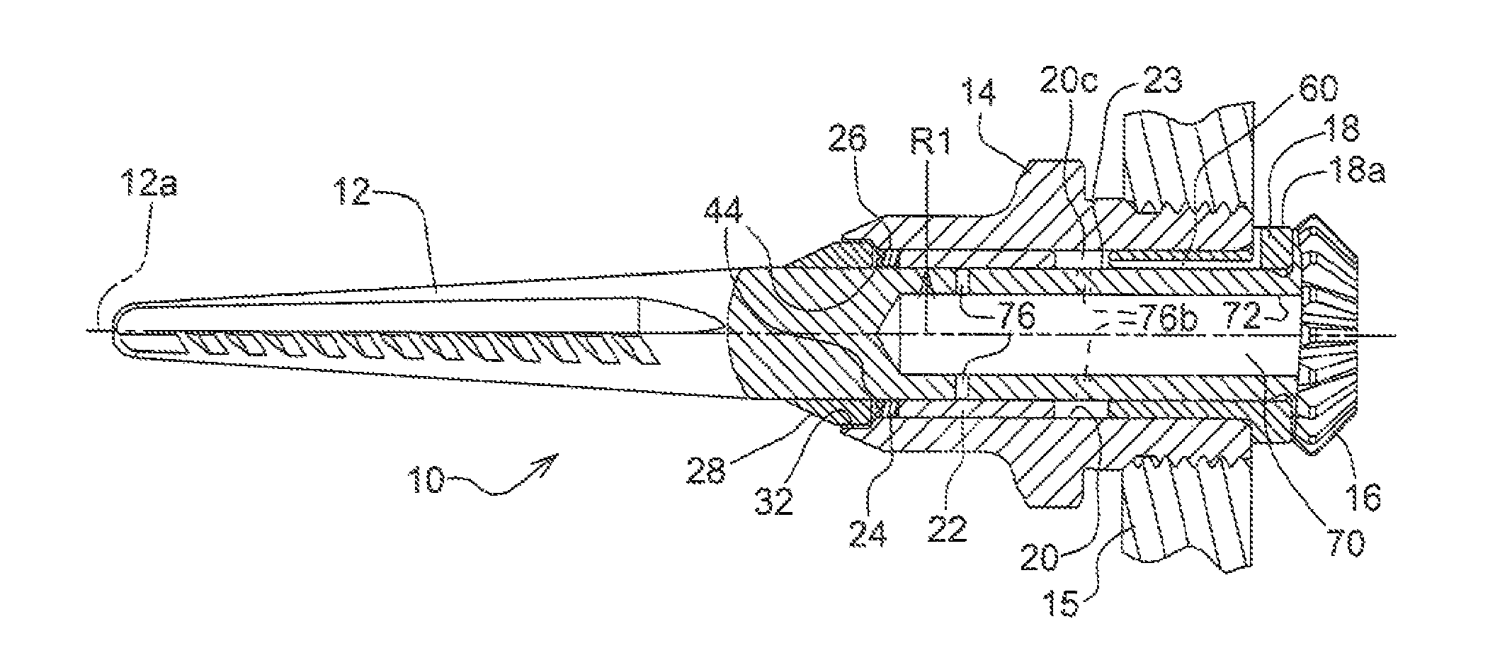
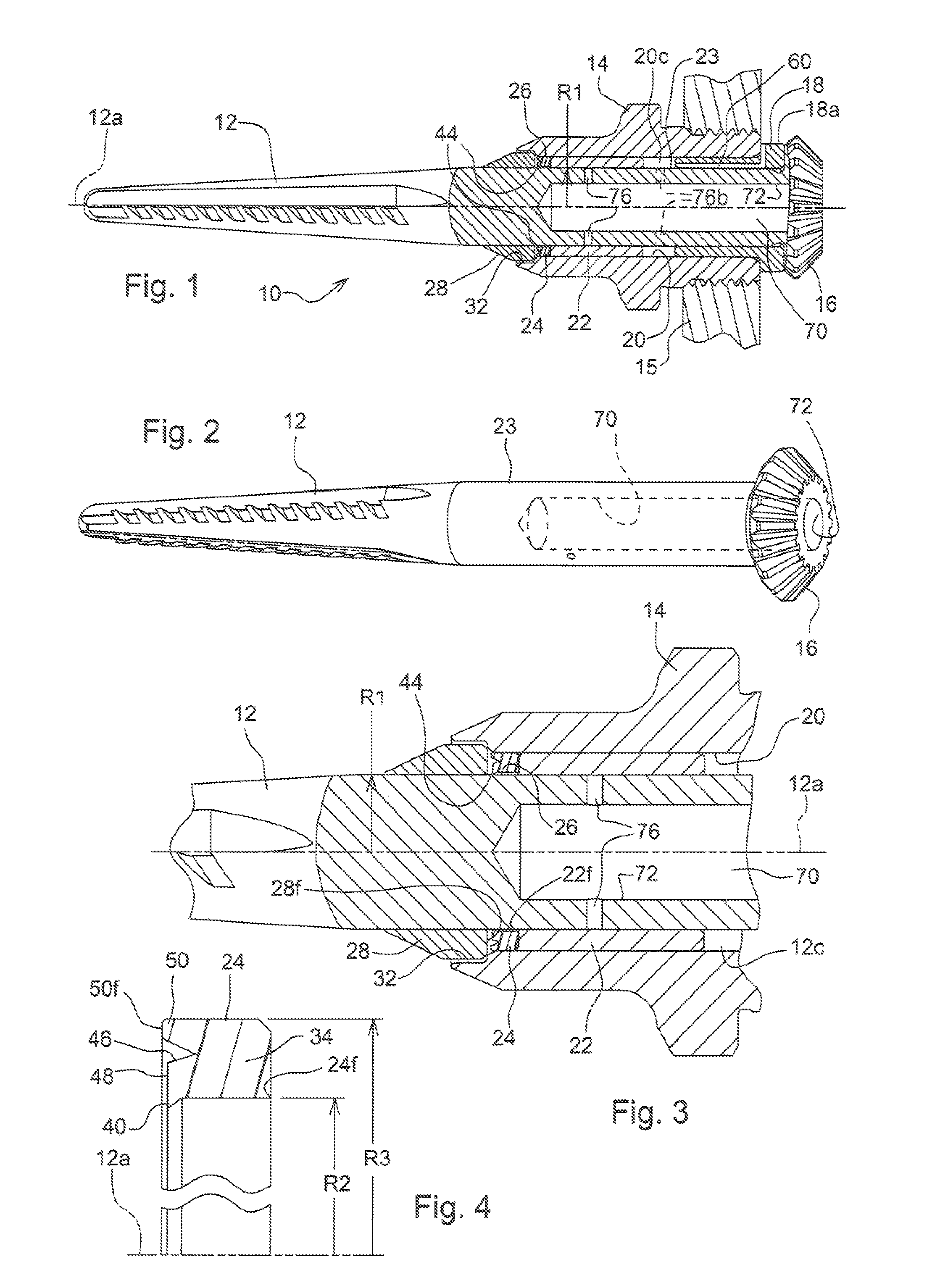
[0016]Referring to FIG. 1, there is shown a spindle assembly 10 including a barbed cotton picker spindle 12 journalled for rotation about a spindle axis 12a within a conventional spindle nut 14. The spindle nut 14 is threaded and adapted to be mounted in an upright cotton picker bar, a portion of which is shown at 15 The spindle 12 includes a bevel gear 16 adapted for mating with a similar bevel gear (not shown) supported for rotation within the picker bar 15. For further details of the picker bar assembly and drive arrangement, reference may be had to U.S. Pat. No. 4,463,543 issued to Hubbard et al and incorporated herein by reference.

[0017]The assembly 10 includes a first or inner bushing 18 press-fitted into a cylindrical bore 20 within the spindle nut 14. A second or outer bushing 22 is press-fitted into the bore 20 at the opposite end of the nut 14 and is offset axially outwardly from the outer end of the bushing 18 to define an annular cavity 20c encircling a cylindrical journ...


PUM


Abstract

A spindle assembly includes a spindle with a blind bore extending along the spindle axis from the drive gear towards the outer end to reduce spindle weight and provide a lubrication reservoir in the spindle. Cross-formed holes extend from the blind bore through to the bearing surface of the spindle. Lubricant from the spindle bars passes into the bore where it is stored and distributed to the journal areas through the small metering apertures. A very low friction seal between the outer bushing and dust collar is pressed into the spindle nut and seals against the polished chrome spindle surface. The seal allows a slight amount of lubricant passage outwardly from the bushings while limiting inward movement of dust towards the bushings.

Description

FIELD OF THE INVENTION[0001]The present invention relates generally to cotton harvesters and, more specifically, to spindles for such cotton harvesters.BACKGROUND OF THE INVENTION[0002]A typical cotton picker includes a plurality of rotating barbed spindles which project into the plants. A picker drum assembly includes a plurality of vertical picker bars which each support a column of rotatable picker spindles. Each spindle is elongated and includes a drive gear which is driven to rotate the spindle about its principle axis as the barbs engage the cotton. The cotton wraps around the spindles and is doffed therefrom by a doffing mechanism which includes a plurality of flexible doffers, one for each row of picking spindles. Cotton pickers typically include from two to six forwardly located row units, each unit supporting a pair of upright picker drums having from twelve to sixteen picker bars. Each picker bar, in turn, rotatably supports up to twenty picker spindles. Several hundred s...

Claims


Application Information

Patent Timeline
Patent Type & Authority Patents(United States)
IPC IPC(8): A01D45/02
CPCA01D46/16
Inventor GOERING, KEVIN JACOBSTUECK, SCOTT F.
Owner DEERE & CO
Why Eureka
Try Eureka