
Multiple hopper charging installation for a shaft furnace

a charging installation and shaft furnace technology, applied in the direction of furnaces, charge manipulation, lighting and heating apparatus, etc., can solve the problems of asymmetric and uneven distribution of bulk materials in the furnace, parts of known charging installations such as the central feeder spout arranged immediately upstream of the chute are subject to considerable wear, and the use of latter installations is limited. , to achieve the effect of reducing the asymmetry of bulk material distribution

Inactive Publication Date: 2012-01-10
PAUL WURTH SA
View PDF22 Cites 6 Cited by
  • Summary
  • Abstract
  • Description
  • Claims
  • Application Information

AI Technical Summary

Benefits of technology

[0005]The invention provides a multiple hopper charging installation for a shaft furnace, which reduces asymmetry of bulk material distribution in the furnace without the use of an additional device dedicated to this purpose.
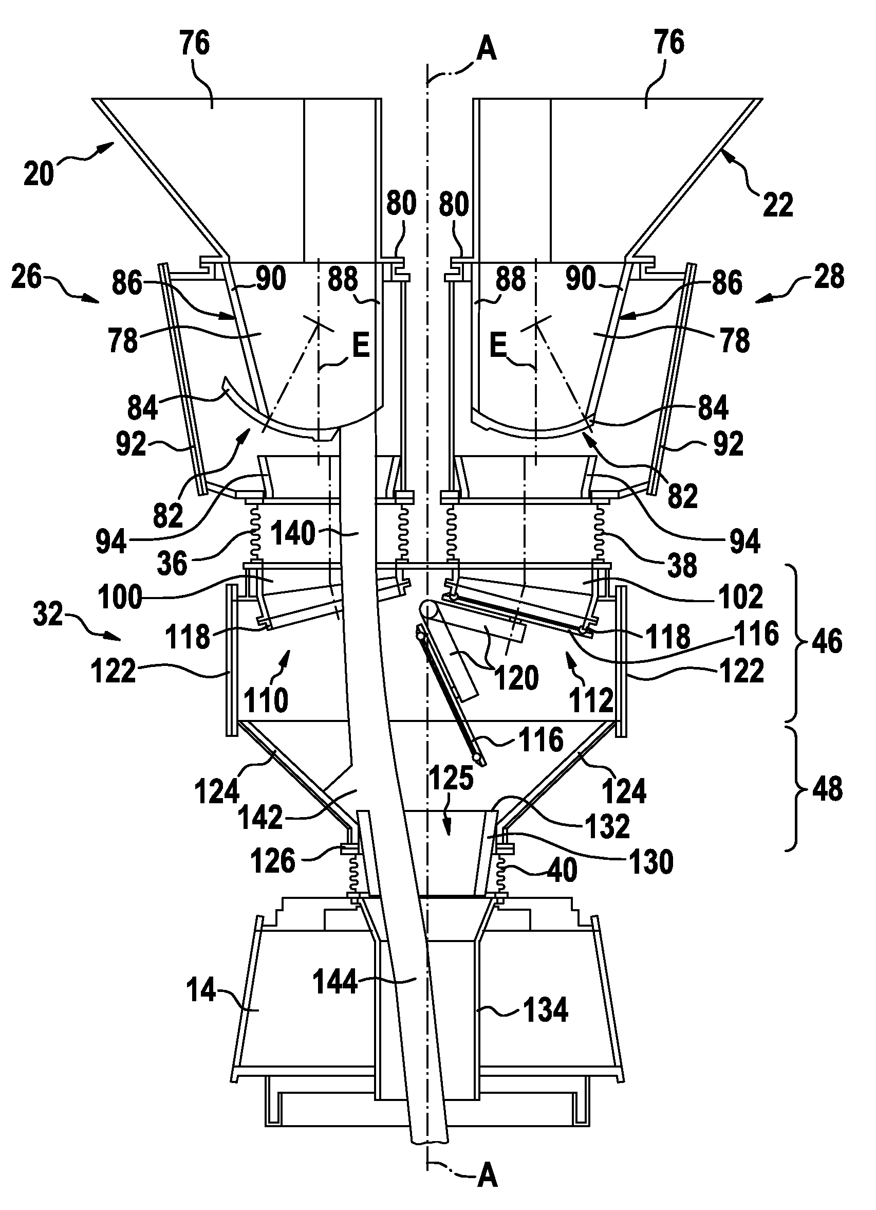
[0007]This configuration allows to obtain, for each hopper, a flow path of charge material which is substantially vertical and nearly centric i.e. coaxial to the central axis. Drawbacks related to slanting flow paths produced in known installations are eliminated.
[0009]Preferably, each funnel part, each outlet portion and each gate valve is configured so that, when the respective material gate valve opens, the substantially vertical outflow of bulk material initially falls straight into a centering insert or a feeder spout. The centering insert or, if no such insert is provided, the feeder spout is arranged concentrically on the central axis downstream of the outlet portions and upstream of the distribution member in order to centre the burden flow onto the distribution member. In this context, initially is to be understood as the time during which there is only a small opening of the gate valve i.e. up to an aperture ratio of several percent e.g. up to 10% of the total valve cross-section. As will be appreciated, avoiding an initial impact in the connecting casing between the hoppers and the rotary distributor (also sometimes called sealing valve housing when the sealing valves are arranged therein) reduces attrition and hence increases lifetime of the affected parts. Furthermore, centering of the flow path is promoted.
[0010]In a further preferred embodiment, each funnel part is configured according to the surface of a frustum of an oblique circular cone. In this case it is beneficial that, in a vertical cross section containing the section line of the funnel part which has maximum slope against the vertical (minimum steepness), this section line has a slope angle of at most 45° and preferably in the range between 30° and 45°. Advantageously, the oblique cone has an included angle of at most 45°. Furthermore, the cone axis of the oblique cone is preferably inclined against the vertical such that in a vertical cross section containing the central axis, the section line of the funnel part proximate to the central axis is vertical or at counterslope, preferably by an angle in the range between 0° and 10°. Each of these measures contributes to promoting a mass flow of bulk material inside the hopper during charging and thereby avoiding segregation of charge material.
[0011]The charging installation preferably further comprises a common sealing valve housing having a funnel-shaped bottom part with an outlet centred on the central axis and communicating with the distribution device and having a top part comprising, for each hopper, an inlet and an associated sealing valve arranged inside the sealing valve housing, wherein an independent material gate housing for the material gate valve of each hopper is connected detachably on top of each inlet of the sealing valve housing. Independent valve housings allow easier access and improved maintenance procedures.
[0012]Advantageously, each material gate housing is fixedly and detachably attached to its associated hopper and flexibly and detachably attached to the top part of the sealing valve housing by means of a compensator. Preferably, the sealing valve housing is detachably attached to the distribution device, either flexibly by means of a compensator or fixedly. This configuration allows to dismantle each valve housing separately whereby maintenance procedures are further improved.

Problems solved by technology

Because of the braking effect of the chute on the bulk material flow, this situation results in an asymmetrical and uneven distribution of bulk material in the furnace.
Furthermore, because of the slanting path of the bulk material some parts of known charging installations such as the central feeder spout arranged immediately upstream of the chute are subject to considerable wear.
The latter installations are however limited in use to charging small coke batches (“coke chimneys”) to the furnace centre.
Although this installation may reduce the problem of uneven and asymmetric distribution, it has the same drawback as the installation known from U.S. Pat. No. 4,599,028 in that it requires an expensive additional mechanism that may be subject to failure and resulting repair down-time.

Method used


Image

  • Multiple hopper charging installation for a shaft furnace
  • Multiple hopper charging installation for a shaft furnace
  • Multiple hopper charging installation for a shaft furnace

Examples


Embodiment Construction

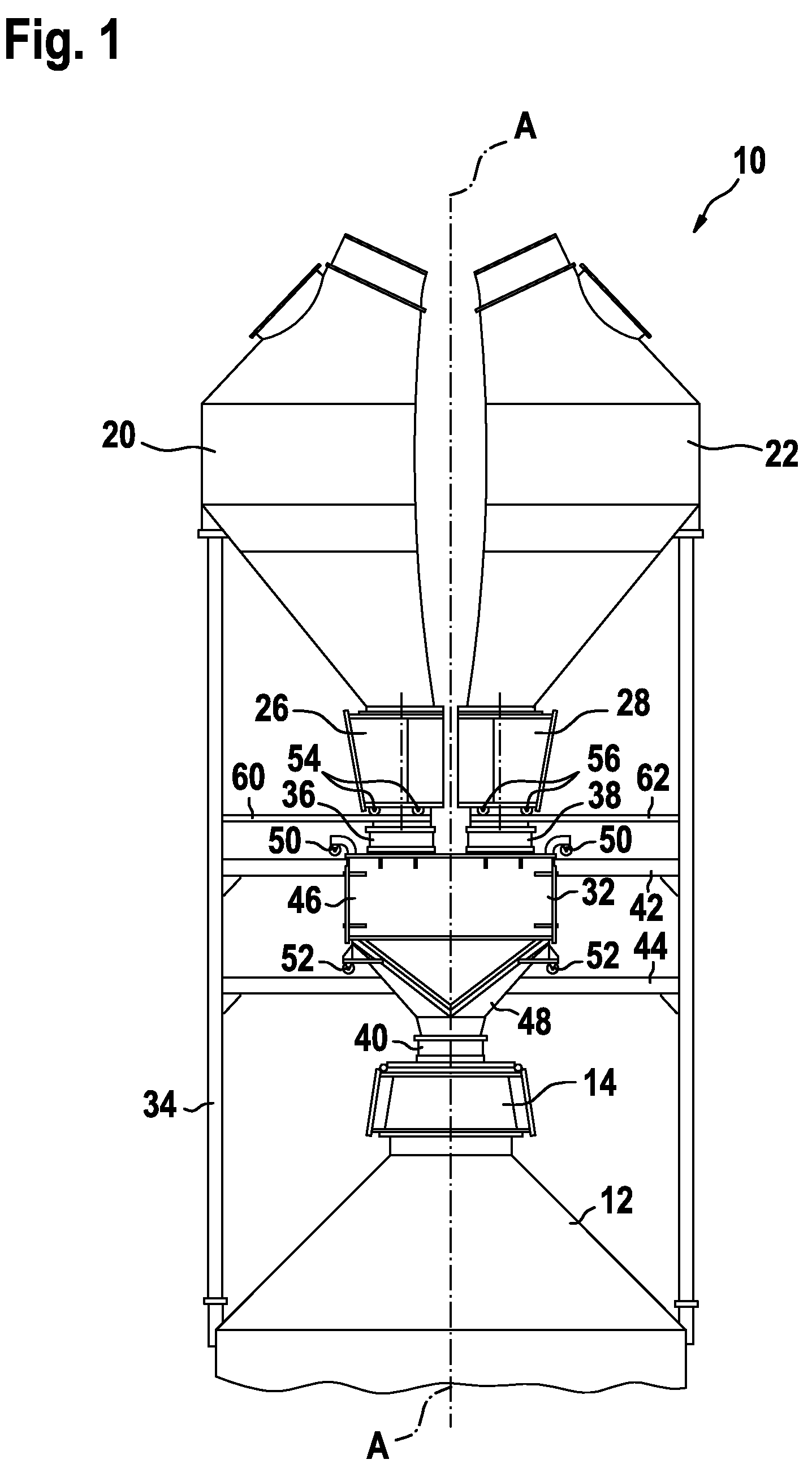
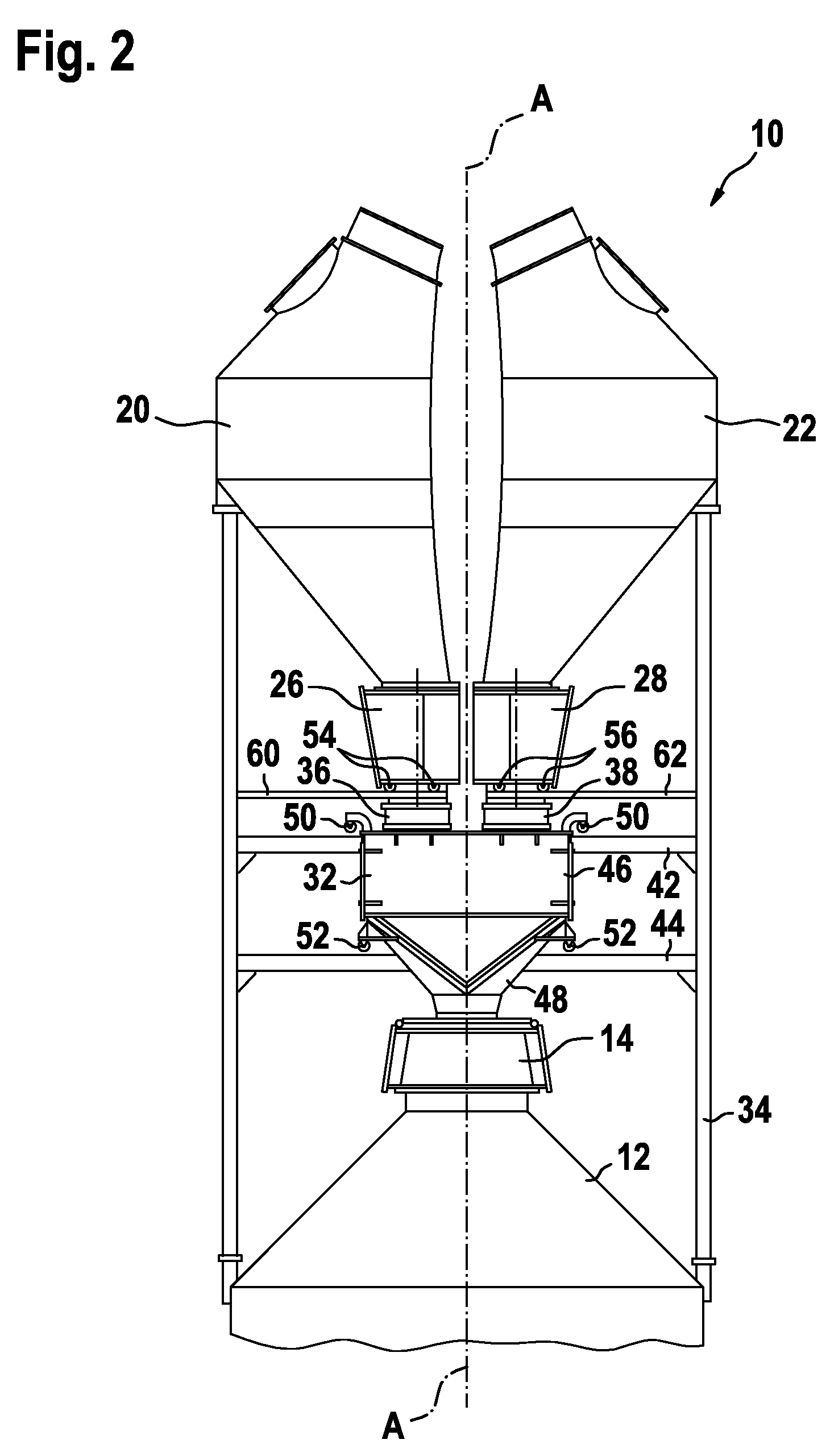
[0027]Referring to FIGS. 1-4, a two hopper charging installation, generally identified by reference numeral 10, will be described in the following first part of the detailed description.

[0028]FIG. 1 shows the two hopper charging installation 10 on top of a blast furnace 12 of which only the throat is partially shown. The charging installation 10 comprises a rotary distribution device 14 arranged as top closure of the throat of the blast furnace 12. The rotary distribution device 14 per se is of a type known from existing BELL LESS TOP installations. For distributing bulk material inside the blast furnace 12, the distribution device 14 comprises a chute (not shown) serving as distribution member. The chute is arranged inside the throat so as to be rotatable about the vertical central axis A of the blast furnace 12 and pivotable about a horizontal axis perpendicular to axis A.

[0029]As seen in FIG. 1, the charging installation 10 comprises a first hopper 20 and a second hopper 22 which...


PUM


Abstract

A multiple hopper charging installation for a shaft furnace includes a rotary distribution device for distributing bulk material in the shaft furnace by rotating a distribution member about a central axis of the shaft furnace and at least two hoppers arranged in parallel and offset from the central axis above the rotary distribution device. Each hopper has a lower funnel part ending in an outlet portion and each hopper has a material gate valve with a shutter member associated to its outlet portion. According to the invention, each funnel part is configured asymmetrically with its outlet portion being eccentric and arranged proximate to the central axis, each outlet portion is oriented vertically so as to produce a substantially vertical outflow of bulk material and each material gate valve has a one-piece shutter member and is configured with its respective shutter member opening in a direction pointing away from the central axis such that any partial valve opening area is located on the side of the associated outlet portion proximate to the central axis.

Description

TECHNICAL FIELD OF THE INVENTION[0001]The present invention generally relates to a charging installation for a shaft furnace, especially for a blast furnace, and in particular to a charging installation comprising at least two hoppers or storage bins for bulk material.BRIEF DISCUSSION OF RELATED ART[0002]BELL LESS TOP charging installations have found widespread use in blast furnaces around the world. They commonly comprise a rotary distribution device equipped with a distribution chute which is rotatable about the vertical central axis of the furnace and pivotable about a horizontal axis perpendicular to the central axis. Basically two different types of BELL LESS TOP charging installations are distinguished. So-called “central-feed” installations have one hopper arranged on the central axis of the furnace above the rotary distribution device for intermediate storage of bulk material to be fed to the distribution device. These installations imply sequential cycles of charging bulk ...

Claims


Application Information

Patent Timeline
Patent Type & Authority Patents(United States)
IPC IPC(8): F27B1/20
CPCB65D88/32C21B7/20F27B1/20F27D3/0032F27D3/0033F27D3/10F27D3/0025F27D2003/105
Inventor LONARDI, EMILETHILLEN, GUYTHINNES, CLAUDELOUTSCH, JEANNOT
Owner PAUL WURTH SA
Learn More