Digital clock and data recovery scheme

a digital clock and data recovery technology, applied in the field of optical receivers, can solve the problems of difficult clock and data recovery (cdr) in digital signal processing (dsp) based optical receivers, and the traditional digital clock recovery scheme is too complex to be implemented at the data rate typically used in optical communication

Active Publication Date: 2012-01-10
RPX CORP
View PDF7 Cites 23 Cited by
  • Summary
  • Abstract
  • Description
  • Claims
  • Application Information

AI Technical Summary

Problems solved by technology

Clock and data recovery (CDR) in digital signal processing (DSP) based optical receivers is challenging if the received signal is distorted by chromatic dispersion, polarization mode dispersion or non-linear effects.
Traditional digital clock recovery schemes are too complex to be implemented at data rates typically used in optical communications.

Method used


Image

  • Digital clock and data recovery scheme
  • Digital clock and data recovery scheme
  • Digital clock and data recovery scheme

Examples


Embodiment Construction

[0018]The invention will be primarily described within the context of digital signal processor (DSP) implementing a clock and data recovery (CDR) function within an optical receiver. However, those skilled in the art and informed by the teachings herein will realize that the invention is also applicable to various other CDR embodiments. Moreover, the various embodiments are primarily presented within the context of a phase modulated optical carrier signal. It will be appreciated by those skilled in the art that the invention may also be utilized within the context of phase and amplitude modulated signals such as quadrature amplitude modulation (QAM) optical carrier signals. In these embodiments, minor modifications for frequency and phase estimation are provided

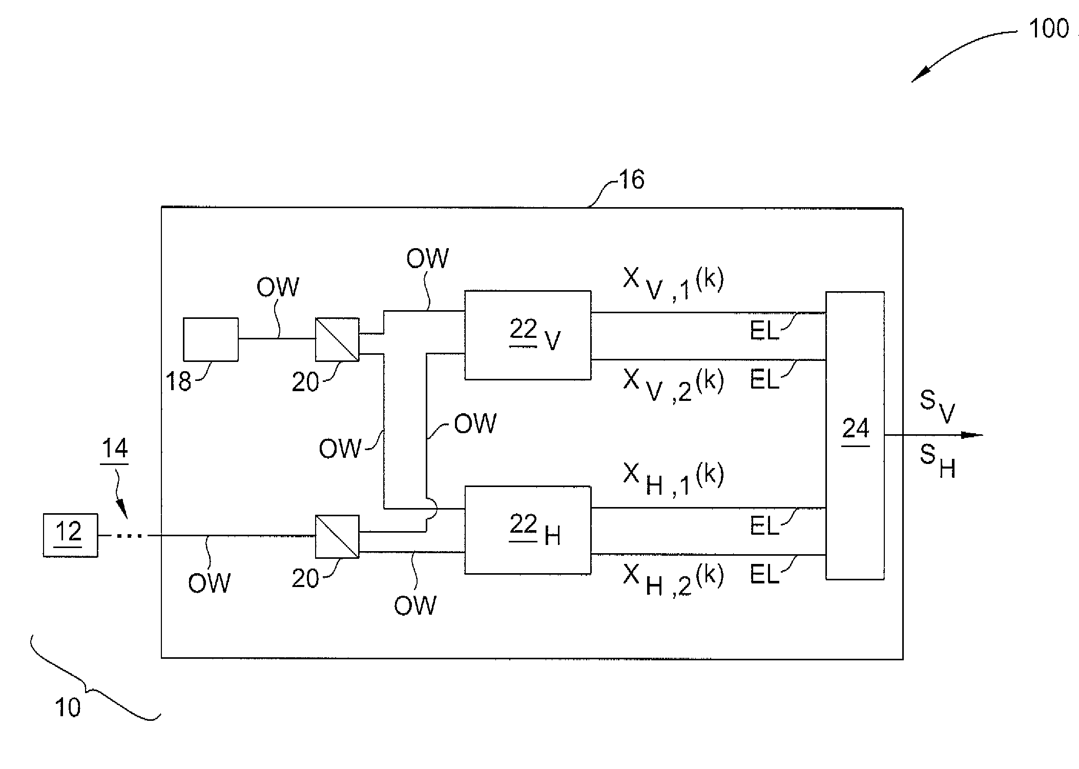
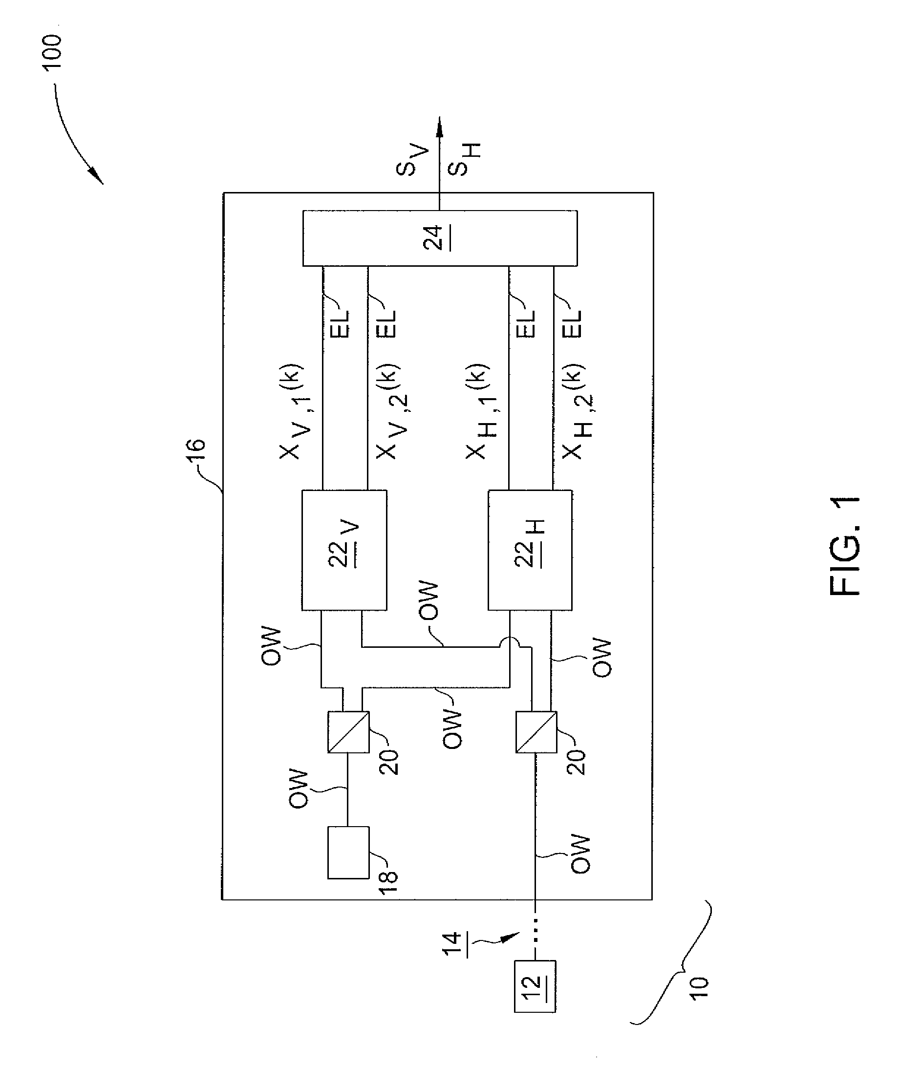
[0019]FIG. 1 depicts a high level block diagram of a polarization-sensitive optical receiver. Specifically, the optical receiver 16 receives a PSK or QAM modulated optical carrier from an optical transmitter 12 via an optical...


PUM


Abstract

A method and apparatus providing clock and data recovery within an optical receiver using three CMA FIR filters with different group delays where filter coefficients are adapted to provide for a filter exhibiting a group delay of one sample period from which symbols for further processing are provided.

Description

FIELD OF THE INVENTION[0001]The invention relates to optical receivers and, more particularly, to clock and data recovery within an optical receiver.BACKGROUND[0002]Clock and data recovery (CDR) in digital signal processing (DSP) based optical receivers is challenging if the received signal is distorted by chromatic dispersion, polarization mode dispersion or non-linear effects. Traditional digital clock recovery schemes are too complex to be implemented at data rates typically used in optical communications.[0003]Clock and data recovery in digital signal processing (DSP) based optical receivers can be performed either in analog domain, digital domain, or in a mixed-mode fashion.[0004]In an analog clock and data recovery scheme, the unprocessed signal before digitization is used for extracting a clock signal. This imposes limits on the maximum signal distortion (chromatic dispersion, polarization-mode dispersion, non-linearity) a receiver can handle independently of post-compensatio...

Claims


Application Information

Patent Timeline
Patent Type & Authority Patents(United States)
IPC IPC(8): H04B10/06
CPCH04B10/61H04B10/611H04B10/6161H04B10/6162H04B10/6163H04B10/6165H04B10/65
Inventor KANEDA, NORIAKILEVEN, ANDREAS BERTOLD
Owner RPX CORP
Why Eureka
Try Eureka